FAA Advisory Circular 43.13-1B
Acceptable Methods, Techniques, and Practices
Aircraft Inspection and Repair
AC 43.13-1B | 7. Aircraft Hardware, Control Cables, and Turnbuckles | 8. Inspection and Repair of Control Cables and Turnbuckles | 7-148. Mechanically-Fabricated Cable Assemblies

9/8/98
cables up to and including 3/8 inch diameter.
The use of sleeves that are fabricated of mate
rials other than copper will require engineering
approval for the specific application by the
FAA.
AC 43.13-1B
(1) Before undertaking a nicopress
splice, determine the proper tool and sleeve for
the cable to be used. Refer to table 7-6 and ta
ble 7-7 for details on sleeves, tools, and the
number of presses required for the various
sizes of aircraft cable. The tool must be in
good working condition and properly adjusted
to ensure a satisfactory splice.
(2) To compress a sleeve, have it well-
centered in the tool groove with the major axis
of the sleeve at right angles to the tool. If the
sleeve appears to be out of line after the press
is started, open the tool, re-center the sleeve,
and complete the press.
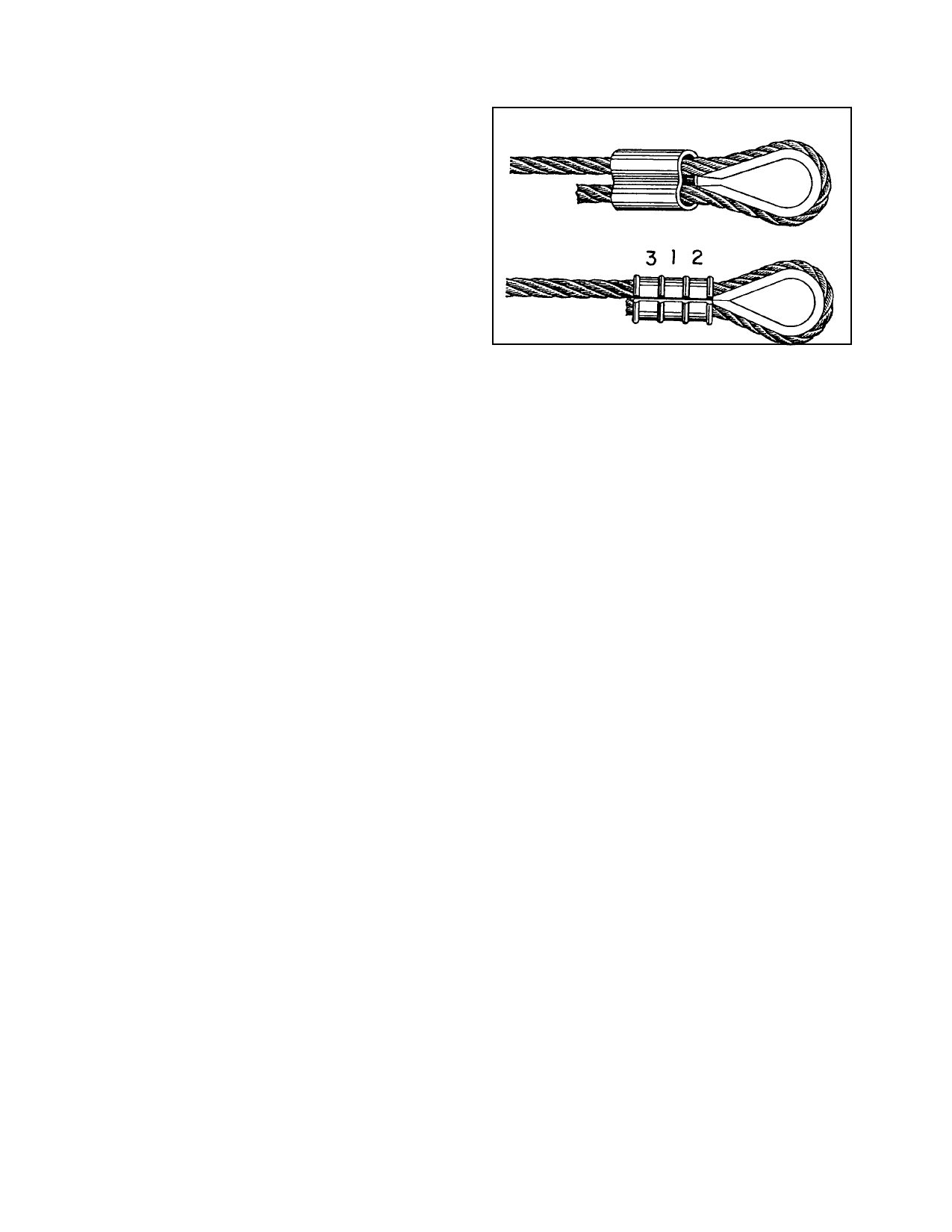
c. Thimble-Eye Splice. Before under
taking a thimble-eye splice, initially position
the cable so the end will extend slightly be
yond the sleeve, as the sleeve will elongate
somewhat when it is compressed. If the cable
end is inside the sleeve, the splice may not
hold the full strength of the cable. It is desir
able that the oval sleeve be placed in close
proximity to the thimble points, so that when
compressed, the sleeve will contact the thimble
as shown in figure 7-14. The sharp ends of the
thimble may be cut off before being used;
however, make certain the thimble is firmly
secured in the cable loop after the splice has
been completed. When using a sleeve requir
ing three compressions, make the center com
pression first, the compression next to the
thimble second, and the one farthest from the
thimble last.
FIGURE 7-14. Typical thimble-eye splice.
strength of the cable. The sleeves should be
positioned as shown in figure 7-12(b), and the
compressions made in the order shown. As in
the case of eye splices, it is desirable to have
the cable ends extend beyond the sleeves suffi
ciently to allow for the increased length of the
compressed sleeves.
e. Stop Sleeves. Stop sleeves may be used
for special cable end and intermediate fittings.
They are installed in the same manner as nico
press oval sleeves.
NOTE: All stop sleeves are plain cop-
per. Certain sizes are colored for iden-
tification.
f. Terminal Gauge. To make a satisfac
tory copper sleeve installation, it is important
that the amount of sleeve pressure be kept uni
form. The completed sleeves should be
checked periodically with the proper gauge.
Hold the gauge so that it contacts the major
axis of the sleeve. The compressed portion at
the center of the sleeve should enter the gauge
opening with very little clearance, as shown in
figure 7-15. If it does not, the tool must be
adjusted accordingly.
d. Lap Splice. Lap or running splices
may also be made with copper oval sleeves.
When making such splices, it is usually neces
sary to use two sleeves to develop the full
g. Other Applications. The preceding in
formation regarding copper oval sleeves and
stop sleeves is based on tests made with flexi
ble aircraft cable. The sleeves may also be
Par 7-148
Page 7-33