FAA Advisory Circular 43.13-1B
Acceptable Methods, Techniques, and Practices
Aircraft Inspection and Repair
AC 43.13-1B | 7. Aircraft Hardware, Control Cables, and Turnbuckles | 8. Inspection and Repair of Control Cables and Turnbuckles | 7-148. Mechanically-Fabricated Cable Assemblies
AC 43.13-1B
TABLE 7-6. Copper oval sleeve data.
Copper oval sleeve stock No.
Cable size
Plain
Plated*
Manual tool
No.
Sleeve length
before com-
pression (ap-
prox.)
(inches)
3/64
18-11-B4
28-11-B4
51-B4-887
3/8
1/16
18-1-C
28-1-C
51-C-887
3/8
3/32
18-2-G
28-2-G
51-G-887
7/16
1/8
18-3-M
28-3-M
51-M-850
9/16
5/32
18-4-P
28-4-P
51-P-850
5/8
3/16
18-6-X
28-6-X
51-X-850
1
7/32
18-8-F2
28-8-F2
51-F2-850
7/8
1/4
18-10-F6
28-10-F6
3-F6-950
1 1/8
5/16
18-13-G9
28-13-G9
3-G9-950
1 1/4
No. 635
Hydraulic tool
dies
3/8
18-23-H5
28-23-H5
Oval H5
1 1/2
7/16
18-24-J8
28-24-J8
Oval J8
1 3/4
1/2
18-25-K8
28-25-K8
Oval K8
1 7/8
9/16
18-27-M1
28-27-M1
Oval M1
2
5/8
18-28-N5
28-28-N5
Oval N5
2 3/8
*Required on stainless cables due to electrolysis caused by different types of metals.
Sleeve length
after com-
pression (ap-
prox.)
(inches)
7/16
7/16
1/2
3/4
7/8
1 1/4
1 1/16
1 1/2
1 5/8
1 7/8
2 1/8
2 1/2
2 5/8
3 1/8
Number of
presses
1
1
1
3
3
4
4
3
3
1
2
2
3
3
9/8/98
Tested
strength
(pounds)
340
550
1,180
2,300
3,050
4,350
5,790
7,180
11,130
16,800
19,700
25,200
31,025
39,200
TABLE 7-7. Copper stop sleeve data.
Cable size (inch)
Sleeve No.
Tool No.
Sleeve
3/64
871-12-B4
51-B4-887
7/32
1/16
871-1-C
51-C-887
7/32
3/32
871-17-J
51-MJ
5/16
(Yellow)
1/8
S71-18-J
51-MJ
5/16
(Red)
5/32
871-19-M
51-MJ
5/16
3/16
871-20-M
51-MJ
5/16
(Black)
7/32
871-22-M
51-MJ
5/8
1/4
871-23-F6
3-F6-950
11/16
5/16
871-26-F6
3-F6-950
11/16
NOTE: All stop sleeves are plain copper. Certain sizes are colored for identification.
Sleeve
11/64
13/64
21/64
21/64
27/64
27/64
7/16
21/32
21/32
Tested strength (pounds)
280
525
600
800
1,200
1,600
2,300
3,500
3,800
used on wire ropes of other construction, if
each specific type of cable is proof-tested ini
tially. Because of variation in rope strengths,
grades, construction, and actual diameters, the
test is necessary to insure proper selection of
materials, the correct pressing procedure, and
an adequate margin of safety for the intended
use.
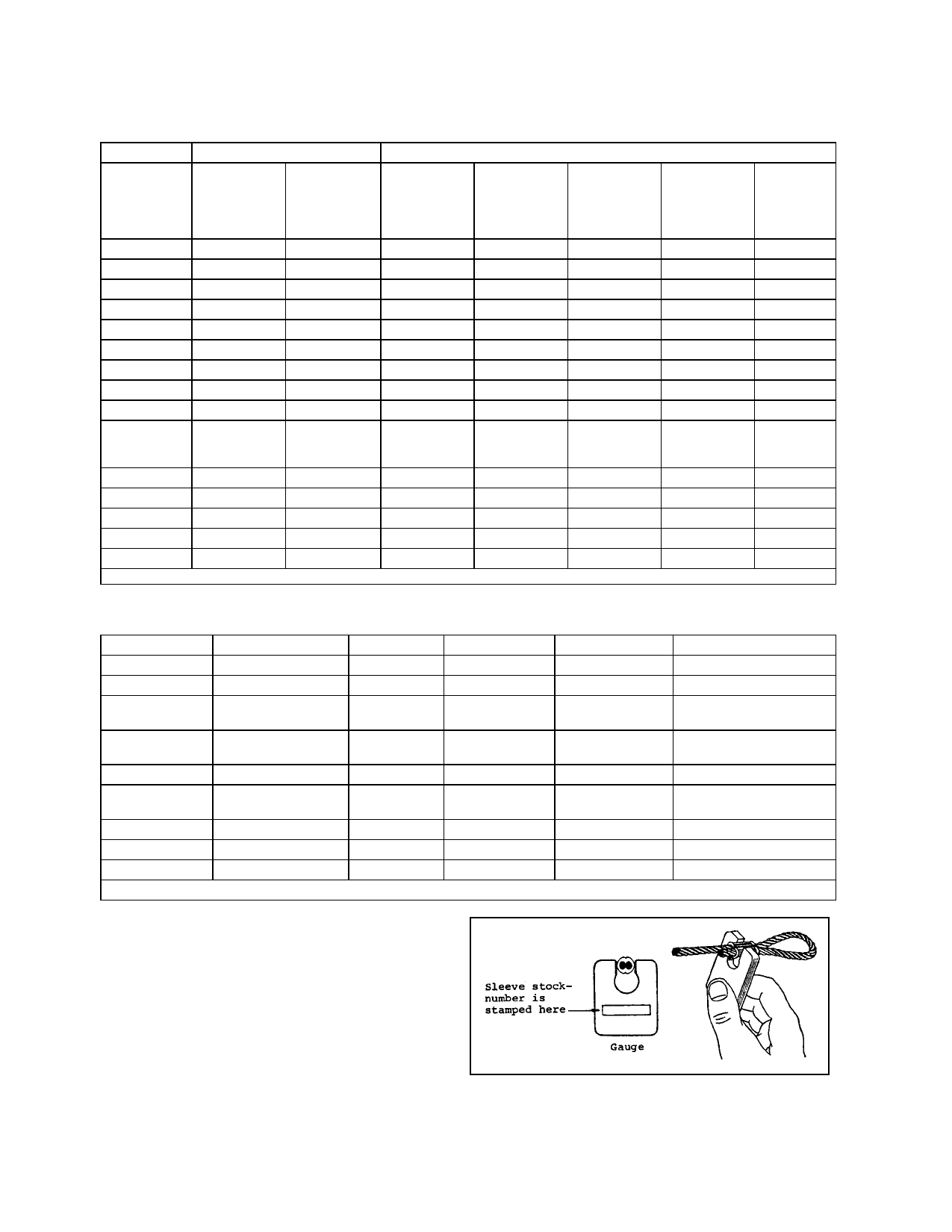
FIGURE 7-15. Typical terminal gauge.
Page 7-34
Par 7-148