FAA Advisory Circular 43.13-1B
Acceptable Methods, Techniques, and Practices
Aircraft Inspection and Repair
AC 43.13-1B | 7. Aircraft Hardware, Control Cables, and Turnbuckles | 8. Inspection and Repair of Control Cables and Turnbuckles | 7-148. Mechanically-Fabricated Cable Assemblies
AC 43.13-1B
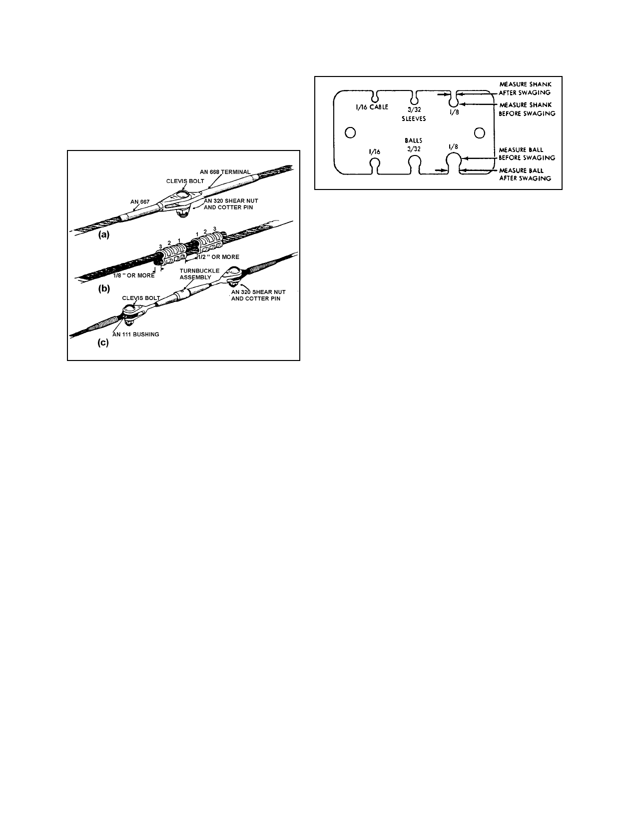
terminal bolted to a clevis terminal. (See fig
ure 7-12(a).) However, this type of splice can
only be used in free lengths of cable which do
not pass over pulleys or through fair-leads.
9/8/98
FIGURE 7-13. Typical terminal gauge.
(4) Cable slippage in terminal. Ensure
that the cable is properly inserted in the termi
nal after the swaging operation is completed.
Instances have been noted wherein only
1/4 inch of the cable was swaged in the termi
nal. Observance of the following precautions
should minimize this possibility.
FIGURE 7-12. Typical cable splices.
(3) Swaged ball terminals. On some
aircraft cables, swaged ball terminals are used
for attaching cables to quadrants and special
connections where space is limited. Single
shank terminals are generally used at the cable
ends, and double shank fittings may be used at
either the end or in the center of the cable.
Dies are supplied with the swaging machines
for attaching these terminals to cables by the
following method.
(a) The steel balls and shanks have a
hole through the center, and are slipped over
the cable and positioned in the desired loca
tion.
(b) Perform the swaging operation in
accordance with the instructions furnished by
the manufacturer of the swaging equipment.
(c) Check the swaged fitting with a
“go no-go” gauge to see that the fitting is
properly compressed, and inspect the physical
condition of the finished terminal. (See fig
ure 7-13.)
(a) Measure the length of the termi
nal end of the fitting to determine the proper
length of cable to be inserted into the barrel of
the fitting.
(b) Lay off this length at the end of
the cable and mark with masking tape. Since
the tape will not slip, it will provide a positive
marking during the swaging process.
(c) After swaging, check the tape
marker to make certain that the cable did not
slip during the swaging operation.
(d) Remove the tape and paint the
junction of the swaged fitting and cable with
red tape.
(e) At all subsequent service inspec
tions of the swaged fitting, check for a gap in
the painted section to see if cable slippage has
occurred.
b. Nicopress Process. A patented process
using copper sleeves may be used up to the full
rated strength of the cable when the cable is
looped around a thimble. This process may
also be used in place of the five-tuck splice on
Page 7-32
Par 7-148