FAA Advisory Circular 43.13-1B
Acceptable Methods, Techniques, and Practices
Aircraft Inspection and Repair
AC 43.13-1B | 7. Aircraft Hardware, Control Cables, and Turnbuckles | 8. Inspection and Repair of Control Cables and Turnbuckles | 7-148. Mechanically-Fabricated Cable Assemblies
9/8/98
AC 43.13-1B
TABLE 7-5. Straight-shank terminal dimensions. (Cross reference AN to MS: AN-666 to MS 21259, AN-667 to
MS 20667, AN-668 to MS 20668, AN-669 to MS 21260.)
Cable size
(inches)
Wire strands
Outside
diameter
1/16
7 x 7
0.160
3/32
7 x 7
.218
1/8
7 x 19
.250
5/32
7 x 19
.297
3/16
7 x 19
.359
7/32
7 x 19
.427
1/4
7 x 19
.494
9/32
7 x 19
.563
5/16
7 x 19
.635
3/8
7 x 19
.703
*Use gauges in kit for checking diameters.
Before swaging
Bore
diameter
Bore
length
0.078
.109
.141
.172
.203
.234
.265
.297
.328
.390
1.042
1.261
1.511
1.761
2.011
2.261
2.511
2.761
3.011
3.510
Swaging
length
0.969
1.188
1.438
1.688
1.938
2.188
2.438
2.688
2.938
3.438
After swaging
Minimum
breaking
strength
(pounds)
Shank
diameter
*
480
0.138
920
.190
2,000
.219
2,800
.250
4,200
.313
5,600
.375
7,000
.438
8,000
.500
9,800
.563
14,400
.625
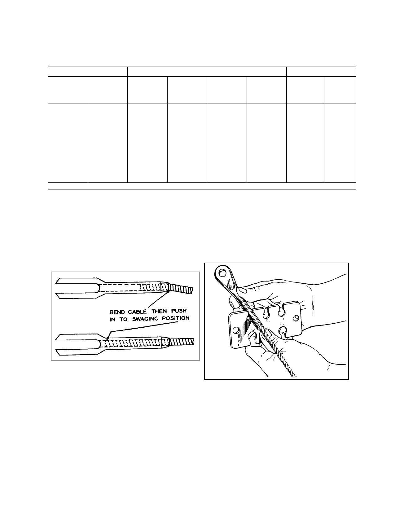
NOTE: If the terminal is drilled com-
pletely through, push the cable into the
terminal until it reaches the approxi-
mate position shown in figure 7-10. If
the hole is not drilled through, insert
the cable until the end rests against the
bottom of the hole.
cable slippage in the terminal and for cut or
broken wire strands.
(e) Using a “go no-go” gauge or a
micrometer, check the terminal shank diameter
as shown in figure 7-11 and table 7-5.
FIGURE 7-10. Insertion of cable into terminal.
(c) Accomplish the swaging opera
tion in accordance with the instructions fur
nished by the manufacturer of the swaging
equipment.
FIGURE 7-11. Gauging terminal shank after swaging.
(f) Test the cable by proof-loading it
to 60 percent of its rated breaking strength.
(d) Inspect the terminal after swaging
to determine that it is free from the die marks
and splits, and is not out-of-round. Check for
(2) Splicing. Completely severed ca
bles, or those badly damaged in a localized
area, may be repaired by the use of an eye
Par 7-148
Page 7-31