FAA Advisory Circular 43.13-1B
Acceptable Methods, Techniques, and Practices
Aircraft Inspection and Repair
AC 43.13-1B | 9. Aircraft Systems and Components | 1. Inspection and Maintenance of Landing Gear | 9-13. Tire and Tube Maintenance
9/27/01
AC 43.13-1B CHG 1
j. Deformation is common in rods and
tubes and usually is noticeable as stretched,
bulged, or bent sections. Because deforma-
tions of this type are difficult to see, feel along
the tube for evidence of this discrepancy. De-
formation of sheet-metal web sections, at
landing-gear component attachment points,
usually can be seen when the area is high-
lighted with oblique lighting.
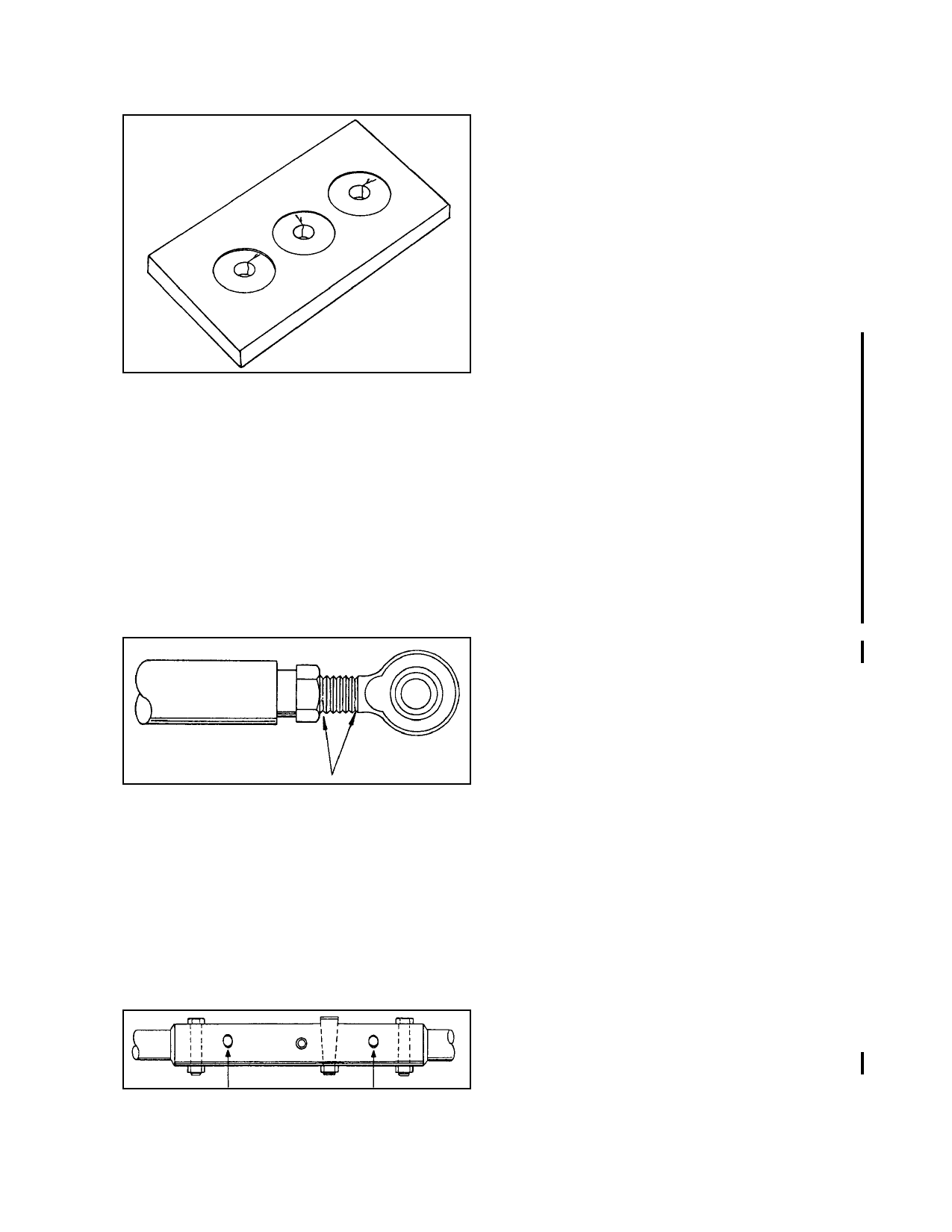
FIGURE 9-4. Typical bolt hole cracks.
f. The usual types of failure in riveted
joints or seams are deformation of the rivet
heads and skin cracks originating at the rivets’
holes.
g. Cracks and subsequent failures of rod
ends usually begin at the thread end near the
bearing and adjacent to or under the jam nut.
(See figure 9-5.)
9-11. SPECIAL INSPECTIONS. When an
aircraft experiences a hard or overweight
landing, the mechanic should perform a special
structural inspection of the aircraft, including
the landing gear. Landing gear support trusses
should be inspected for cracked welds, sheared
bolts and rivets, and buckled structures.
Wheels and tires should be inspected for
cracks and cuts, and upper and lower wing sur-
faces should be inspected for wrinkles, defor-
mation, and loose or sheared rivets. If any
damage is found, a detailed inspection is rec-
ommended.
FIGURE 9-5. Typical rod-end cracks.
h. Cracks develop primarily along the
edge of the weld adjacent to the base metal and
along the centerline of the bead.
i. Elongated holes are especially preva-
lent in taper-pin holes and bolt holes or at the
riveted joints of torque tubes and push-pull
rods. (See figure 9-6.)
9-12. RETRACTION TESTS. Periodically
perform a complete operational check of the
landing gear retraction system. Inspect the
normal extension and retraction system, the
emergency extension system, and the indicat-
ing and emergency warning system. Deter-
mine that the actuating cylinders, linkage, slide
tubes, sprockets, chain or drive gears, gear
doors, and the up-and-down locks are in good
condition and properly adjusted and lubricated,
and the wheels have adequate clearance in the
wheel wells. In addition, an electrical conti-
nuity check of micro-switches and associated
wiring is recommended. Only qualified per-
sonnel should attempt adjustments to the gear
position and warning system micro-switches.
Follow the manufacturer’s recommendations.
FIGURE 9-6. Typical torque tube bolt hole elongation.
9-13. TIRE AND TUBE MAINTE-
NANCE. A program of tire maintenance can
minimize tire failures and increase tire service
life.
Par 9-10
Page 9-9