FAA Advisory Circular 43.13-1B
Acceptable Methods, Techniques, and Practices
Aircraft Inspection and Repair
AC 43.13-1B | 9. Aircraft Systems and Components | 1. Inspection and Maintenance of Landing Gear | 9-10. Types of Landing Gear Problems
AC 43.13-1B CHG 1
9/27/01
the runner using glue and bolts. Bent or torn
metal runners may be straightened if minor
bending has taken place and minor tears may
be repaired in accordance with procedures rec-
ommended in Chapter 4, Metal Structure,
Welding, and Brazing.
d. Ski Pedestals.
(1) Tubular Pedestals. Damaged ped-
estals made of steel tubing may be repaired by
using tube splices as shown in the chapter on
welding.
(2) Cast Pedestals. Consult a Federal
Aviation Administration (FAA) representative
on the repair of cast pedestals.
9-10. TYPES OF LANDING GEAR
PROBLEMS. During inspection and before
removing any accumulated dirt, closely ob-
serve the area being inspected while the wing-
tips are gently rocked up and down. Excessive
motion between normally close-fitting landing
gear components may indicate wear, cracks, or
improper adjustment. If a crack exists, it will
generally be indicated by dirt or metallic parti-
cles which tend to outline the fault. Seepage
of rust inhibiting oils, used to coat internal sur-
faces of steel tubes, also assists in the early
detection of cracks. In addition, a sooty, oily
residue around bolts, rivets, and pins is a good
indication of looseness or wear.
a. Thoroughly clean and re-inspect the
landing gear to determine the extent of any
damage or wear. Some components may re-
quire removal and complete disassembly for
detailed inspection. Others may require a spe-
cific check using an inspection process such as
dye penetrant, magnetic particle, radiographic,
ultrasonic, or eddy current. The frequency,
degree of thoroughness, and selection of in-
spection methods are dependent upon the age,
use, and general condition of the landing gear.
b. Inspect the aircraft or landing gear
structure surrounding any visible damage to
ensure that no secondary damage remains un-
detected. Forces can be transmitted along the
affected member to remote areas where subse-
quent normal loads can cause failure at a later
date.
c. Prime locations for cracks on any
landing gear are bolts, bolt holes, pins, rivets,
and welds. The following are typical locations
where cracks may develop.
d. Most susceptible areas for bolts are at
the radius between the head and the shank, and
in the location where the threads join the
shank, as shown in figure 9-2.
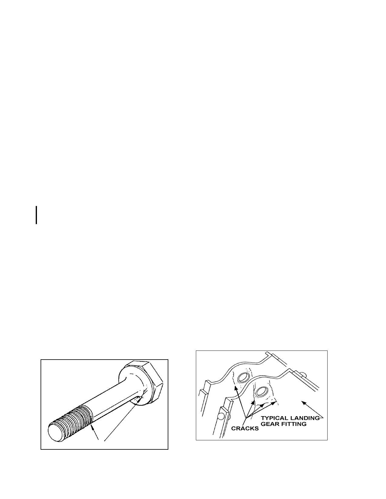
e. Cracks primarily occur at the edge of
bolt holes on the surface and down inside the
bore. (See figures 9-3 and 9-4.)
FIGURE 9-2. Typical bolt cracks.
Page 9-8
FIGURE 9-3. Typical cracks near bolt holes.
Par 9-9