FAA Advisory Circular 43.13-1B
Acceptable Methods, Techniques, and Practices
Aircraft Inspection and Repair
AC 43.13-1B | 8. Engines, Fuel, Exhaust, and Propellers | 1. Engines | 8-15. Spark Plugs
9/8/98
AC 43.13-1B
classification of spark plugs according to their
ability to transfer heat from the firing end of
the spark plug to the cylinder head.
(1) Spark plugs have been classified as
“hot,” “normal,” and “cold.” However, these
terms may be misleading because the heat
range varies through many degrees of tem-
perature from extremely hot to extremely cold.
Thus the words “hot,” “cold,” and “normal” do
not necessarily tell the whole story.
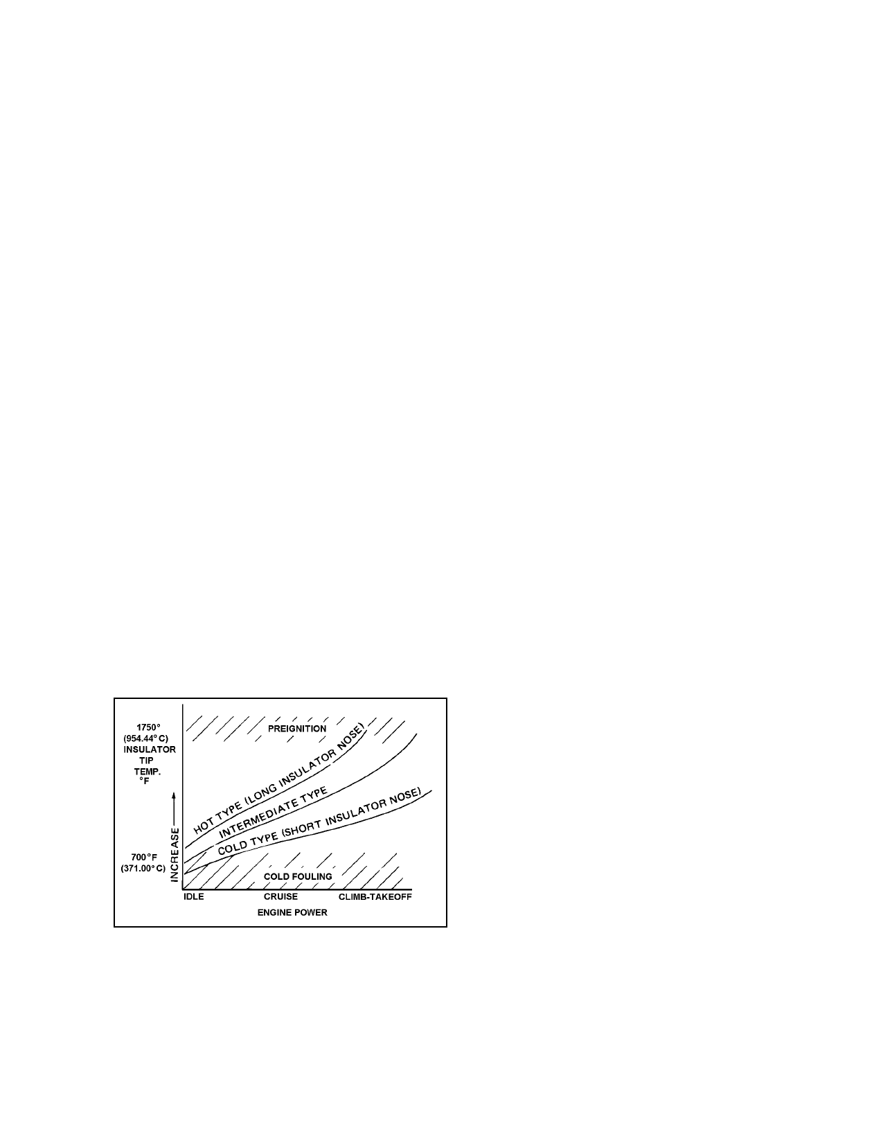
(2) Since the insulator is designed to be
the hottest part of the spark plug, its tempera-
ture can be related to the pre-ignition and
fouling regions as shown in figure 8-2. Pre-
ignition is likely to occur if surface areas in the
combustion chamber exceed critical limits or if
the spark plug core nose temperature exceeds
1,630 °F (888 °C). However, fouling or short-
circuiting of the plug due to carbon deposits is
likely to occur if the insulator tip temperature
drops below approximately 800 °F (427 °C).
Since spark plugs must operate between fairly
well-defined temperature limits, they must be
supplied in various heat ranges to meet the re-
quirements of different engines under a variety
of operating conditions.
operate as hot as possible at low speeds and
light loads and as cool as possible under
cruising and takeoff power. Plug performance,
therefore, depends on the operating tempera-
ture of the insulator nose, with the most desir-
able temperature range falling between
1,000 °F and 1,250 °F (538 °C and 677 °C).
(4) Fundamentally, an engine which
runs hot requires a relatively cold spark plug,
whereas an engine which runs cool requires a
relatively hot spark plug. If a hot spark plug is
installed in an engine which runs hot, the spark
plug tip will be overheated and cause pre-
ignition. If a cold spark plug is installed in an
engine which runs cool, the tip of the spark
plug will collect unburned carbon, causing
fouling of the plug. The principal factors gov-
erning the heat range of aircraft spark plugs
are:
(a) the distance between the copper
sleeve around the insulator and the insulator
tip;
(b) the thermal conductivity of the
insulating material;
(c) the thermal conductivity of the
electrode;
(d) the rate of heat transfer between
the electrode and the insulator;
(e) the shape of the insulator tip;
(f) the distance between the insulator
tip and the shell; and
FIGURE 8-2. Chart of spark plug temperature ranges.
(3) From the engineering standpoint,
each individual plug must be designed to offer
the widest possible operating range. This
means that a given type of spark plug should
(g) the type of outside gasket used.
(5) “Hot” plugs have a long insulator
nose; thereby, creating a long heat transfer
path, whereas “cold” plugs have a relatively
short insulator to provide a rapid transfer of
heat to the cylinder head. (See figure 8-3.)
Par 8-15
Page 8-9