FAA Advisory Circular 43.13-1B
Acceptable Methods, Techniques, and Practices
Aircraft Inspection and Repair
AC 43.13-1B | 8. Engines, Fuel, Exhaust, and Propellers | 1. Engines | 8-14. Compression Testing of Aircraft Engine Cylinders
9/27/01
AC 43.13-1B CHG 1
a. Differential Compression Test. The
most common type of compression tester cur-
rently in use is the differential pressure-type
tester. It provides a cross-reference to validate
the readings obtained and tends to assure that
the cylinder is defective before it is removed.
Before beginning a compression test, consider
the following points:
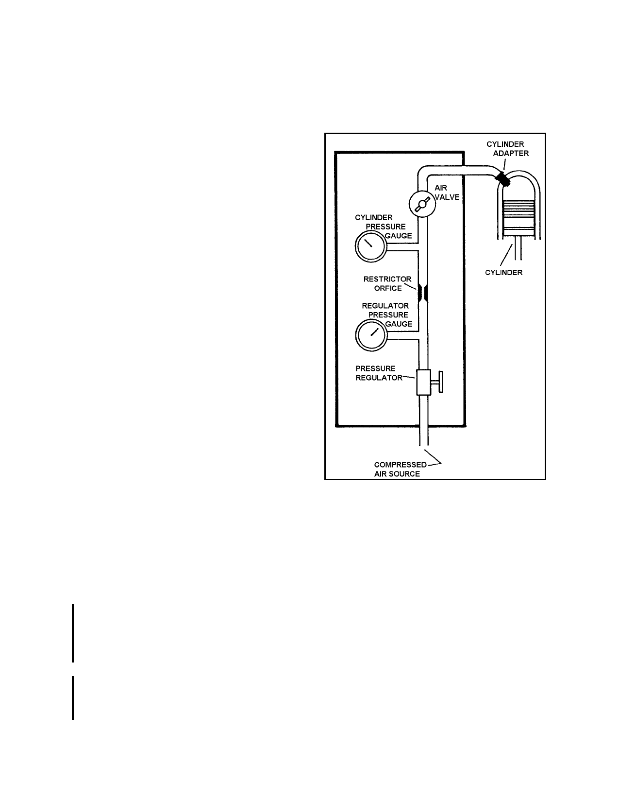
(3) A typical schematic diagram of the
differential pressure tester is shown in
figure 8-1.
(1) When the spark plugs are removed
from the engine, identify them to coincide with
the cylinder and location from which they were
removed. Close examination of the plugs will
reveal the actual operating conditions and aid
in diagnosing problems within each individual
cylinder.
(2) The operating and maintenance rec-
ords of the engine should be reviewed. Rec-
ords of previous compression tests are of as-
sistance in determining progressive wear con-
ditions and help to establish the necessary
maintenance corrective actions.
b. Differential Pressure Compression
Test. The differential pressure tester is de-
signed to check the compression of aircraft en-
gines by measuring the leakage through the
cylinders caused by worn or damaged compo-
nents. The operation of the compression tester
is based on the principle that, for any given air-
flow through a fixed orifice, a constant pres-
sure drop across that orifice will result. The
restrictor orifice dimensions in the differential
pressure tester should be sized for the particu-
lar engine as follows:
(1) For an engine cylinder having less
than a 5.00-inch bore; 0.040-inch orifice di-
ameter; .250 inch long; and a 60-degree ap-
proach angle.
(2) For an engine cylinder with 5.00
inch bore and over: 0.060 inch orifice diame-
ter, .250 inch long, 60 degree approach angle.
FIGURE 8-1. Schematic of differential pressure com-
pression tester.
(4) As the regulated air pressure is ap-
plied to one side of the restrictor orifice with
the air valve closed, there will be no leakage
on the other side of the orifice and both pres-
sure gauges will read the same. However,
when the air valve is opened and leakage
through the cylinder increases, the cylinder
pressure gauge will record a proportionally
lower reading.
(5) While performing the check the
following procedures are listed to outline the
principles involved, and are intended to sup-
plement the manufacturer’s instructions for the
particular tester being used.
Par 8-14
Page 8-7