FAA Advisory Circular 43.13-1B
Acceptable Methods, Techniques, and Practices
Aircraft Inspection and Repair
AC 43.13-1B | 4. Metal Structure, Welding, and Brazing | 4. Metal Repair Procedures | 4-57. Riveting
AC 43.13-1B
9/8/98
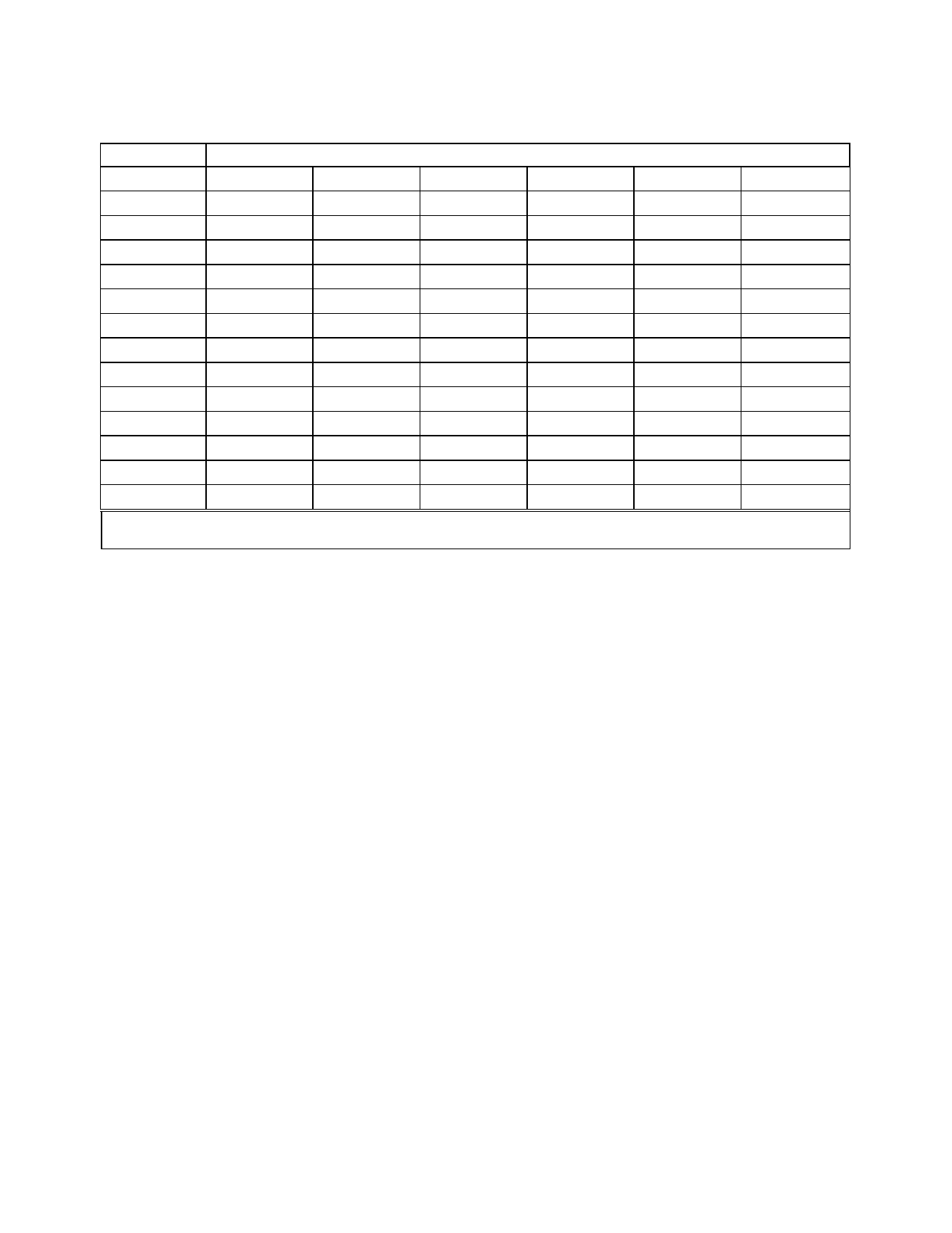
TABLE 4-6. Recommended radii for 90-degree bends in aluminum alloys.
Alloy and
temper
2024-01
2024-T31, 2
2024-T61
5052-0
5052-H32
5052-H34
5052-H36
5052-H38
6061-0
6061-T4
6061-T6
7075-0
7075-T61
0.016
0
1½t-3t
2t-4t
0
0
0
0-1t
½t-1½t
0
0-1t
0-1t
0
2t-4t
Approximate sheet thickness (t) (inch)
0.032
0.064
0.128
0.182
0-1t
0-1t
0-1t
0-1t0-1t
2t-4t
3t-5t
4t-6t
4t-6t
3t-5t
3t-5t
4t-6t
5t-7t
0
0-1t
0-1t
0-1t
0
½t-1t
½t-1½t
½t-1½t
0
½t-1½t
1½t-2½t
1½t-2½t
½t-1½t
1t-2t
1½t-3t
2t-4t
1t-2t
1½t-3t
2t-4t
3t-5t
0-1t
0-1t
0-1t
0-1t
0-1t
½t-1½t
1t-2t
1½t-3t
½t-1½t
1t-2t
1½t-3t
2t-4t
0-1t
0-1t
½t-1½t
1t-2t
3t-5t
4t-6t
5t-7t
5t-7t
0.258
0-1t
5t-7t
6t-10t
0-1t
½t-1½t
2t-3t
2t-4t
4t-6t
0-1t
2½t-4t
3t-4t
1½t-3t
6t-10t
1 Alclad sheet may be bent over slightly smaller radii than the corresponding tempers of uncoated alloy.
2 Immediately after quenching, this alloy may be formed over appreciably smaller radii.
b. To determine setback for a bend of
more or less than 90 degrees, a correction
known as a K-factor must be applied to find
the setback.
(1) Table 4-7 shows a chart of
K-factors. To find the setback for any degree
of bend, multiply the sum of the bend radius
and metal thickness by the K-value for the an
gle through which the metal is bent.
(2) Figure 4-3 shows an example of a
piece of 0.064 inch sheet metal bent
through 45 degrees to form an open angle
of 135 degrees. For 45 degrees, the K-factor
is 0.41421. The setback, or the distance from
the mold point to the bend tangent line, is:
Setback = K(BR + MT)
= 0.41421 (0.25 + 0.064)
= 0.130 inches
(3) If a closed angle of 45 degrees is
formed, the metal must be bent
through 135 degrees. The K-factor for 135 de
grees is 2.4142, so the setback, or distance
from the mold point to the bend tangent line, is
0.758 inch.
4-57. RIVETING.
a. The two major types of rivets used in
aircraft are the common solid shank rivet,
which must be driven using an air-driven rivet
gun and bucking bar; and special (blind) rivets,
which are installed with special installation
tools. Design allowables for riveted assem
blies are specified in MIL-HDBK-5.
(1) Solid shank rivets are used widely
during assembly and repair work. They are
identified by the material of which they are
made, the head type, size of shank, and temper
condition.
Page 4-14
Par 4-56