FAA Advisory Circular 43.13-1B
Acceptable Methods, Techniques, and Practices
Aircraft Inspection and Repair
AC 43.13-1B | 4. Metal Structure, Welding, and Brazing | 4. Metal Repair Procedures | 4-56. Setback
9/8/98
AC 43.13-1B
MIL-HDBK-5 and corresponding specifica
tions. If the heat-treatment produces warping,
straighten the parts immediately after quench
ing. Heat-treat riveted parts before riveting, to
preclude warping and corrosion.
a. Quenching. Quench material from the
solution heat-treating temperature as rapidly as
possible after removal from the furnace.
Quenching in cold water is preferred, although
less drastic chilling (hot or boiling water, or
airblast) is sometimes employed for bulk sec
tions, such as forgings, to minimize quenching
stresses.
b. Reheating at Temperatures Above
Boiling Water. Reheating of 2017 and
2024 alloys above 212 °F tend to impair the
original heat treatment. Therefore, reheating
above 212 °F, including the baking of primers,
is not acceptable without subsequent complete
and correct heat treatment.
4-55. BENDING METAL. When describ
ing a bend in aviation, the term “bend radii” is
used to refer to the inside radius. Require
ments for bending the metal to various shapes
are frequently encountered. When a metal is
bent, it is subjected to changes in its grain
structure, causing an increase in its hardness.
sheet before the bending or shaping is per
formed. Before bending, smooth all rough
edges, remove burrs, and drill relief holes at
the ends of bend lines and at corners; to pre
vent cracks from starting. Bend lines should
preferably be made to lie at an angle to the
grain of the metal (preferably 90 degrees).
c. Bend radii (BR) in inches for a spe
cific metal composition (alloy) and temper is
determined from table 4-6. For example, the
minimum bend radii for 0.016 thick 2024-T6
(alloy and temper) is found is found to be
2 to 4 times the material thickness or
0.032 to 0.064.
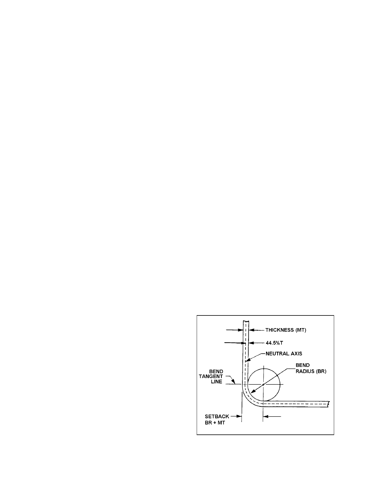
4-56. SETBACK.
a. Setback is a measurement used in sheet
metal layout. It is the distance the jaws of a
brake must be setback from the mold line to
form a bend. For a 90 degree bend, the point
is back from the mold line to a distance equal
to the bend radius plus the metal thickness.
The mold line is an extension of the flat side of
a part beyond the radius. The mold line di
mension of a part, is the dimension made to
the intersection of mold lines, and is the di
mension the part would have if its corners had
no radius. (See figure 4-2.)
a. The minimum radius is determined by
the composition of the metal, its temper, and
thickness. Table 4-6 shows the recommended
radius for different types of aluminum. Note
that the smaller the thickness of the material,
the smaller the recommended minimum bend
radius, and that as the material increases in
hardness, the recommended bend radii in
creases.
b. When using layout techniques, the
mechanic must be able to calculate exactly
how much material will be required for the
bend. It is easier to lay out the part on a flat
FIGURE 4-2. Setback for a 90-degree bend.
Par 4-54
Page 4-13