FAA Advisory Circular 43.13-1B
Acceptable Methods, Techniques, and Practices
Aircraft Inspection and Repair
AC 43.13-1B | 3. Fiberglass and Plastics | 1. Repair of Light Load Laminate Structures | 3-4. Sample Bagging and Curing Process
9/8/98
AC 43.13-1B
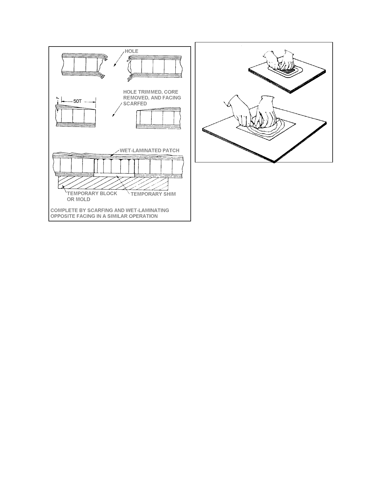
FIGURE 3-8. Carefully cut through each layer of fiber
glass cloth and remove it from the damaged area.
FIGURE 3-7. Typical scarf joint repair.
(1) The configuration of the repair
should be that which will remove the least
amount of sound material. Extend the
cleaned-out area for a distance equal to the
number of plies to be removed, less 1 inch.
For example, if you must remove three plies,
extend the repair for 2 inches beyond the
cleaned-out area. Each layer should be 1 inch
beyond the layer below. Use a sharp knife or
other type of cutter to cut through the top layer,
being careful not to damage the underneath
layer. Use several passes with the knife rather
than one deep cut. (See figure 3-8.)
(2) Begin with one corner of the patch
and carefully pry it loose and peel it up until
all of the layer is removed. Next, mark the ex
posed layer 1/2 inch inside the opening and
carefully cut and remove it. Continue until
you have removed all of the damaged or de
laminated layers.
(3) Lightly sand, then scrub the entire
area with an acceptable cleanser. Prepare the
patches exactly as you did for the scarf
method, cutting each layer to exactly the size
of the material removed. Brush in a coat of
resin, lay in the patch of the smallest size, and
carefully work out all of the air bubbles from
the resin. Now, lay in the next larger size
patch to lock the first layer of fiberglass cloth
into place. Repeat the process until the dam
age area is filled.
(4) Butt the top layer of cloth to the
opening in the face ply and cover the entire re
pair with peel ply. Carefully work all of the air
bubbles out of the resin and put pressure on the
repair with either sandbags, or another appro
priate method, such as vacuum bagging. (See
figure 3-9.) After the top repair has hardened,
repeat the process on the bottom.
3-4. SAMPLE BAGGING AND CURING
PROCESS. Figure 3-9 shows a typical bag
ging arrangement for a localized repair in
which patch plies of prepreg are cured with a
layer of adhesive, and a heating blanket is used
to supply heat.
Par 3-3
Page 3-5