FAA Advisory Circular 43.13-1B
Acceptable Methods, Techniques, and Practices
Aircraft Inspection and Repair
AC 43.13-1B | 7. Aircraft Hardware, Control Cables, and Turnbuckles | 8. Inspection and Repair of Control Cables and Turnbuckles | 7-149. Cable System Inspection
9/8/98
AC 43.13-1B
7-149. CABLE SYSTEM INSPECTION.
Aircraft cable systems are subject to a variety
of environmental conditions and deterioration.
Wire or strand breakage is easy to visually rec
ognize. Other kinds of deterioration such as
wear, corrosion, and/or distortion are not easily
seen; therefore, control cables should be re
moved periodically for a more detailed inspec
tion.
a. At each annual or 100 hour inspec-
tion, all control cables must be inspected for
broken wires strands. Any cable assembly that
has one broken wire strand located in a critical
fatigue area must be replaced.
must be made since a broken wire will not al
ways protrude or stick out, but may lie in the
strand and remain in the position of the helix
as it was manufactured. Broken wires of this
type may show up as a hairline crack in the
wire. If a broken wire of this type is sus
pected, further inspection with a magnifying
glass of 7 power or greater, is recommended.
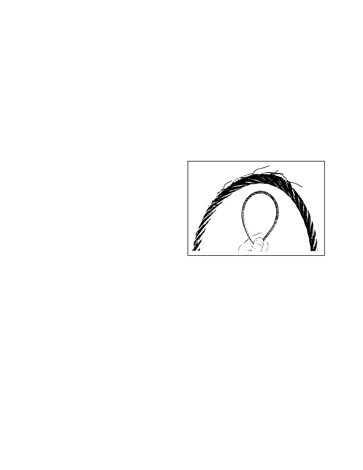
Figure 7-16 shows a cable with broken wires
that was not detected by wiping, but was found
during a visual inspection. The damage be
came readily apparent when the cable was re
moved and bent as shown in figure 7-16.
b. A critical fatigue area is defined as the
working length of a cable where the cable runs
over, under, or around a pulley, sleeve, or
through a fair-lead; or any section where the
cable is flexed, rubbed, or worked in any man
ner; or any point within 1 foot of a swaged-on
fitting.
c. A swaged-on fitting can be an eye,
fork, ball, ball and shank, ball and double
shank, threaded stud, threaded stud and turn
buckle, compression sleeve, or any hardware
used as a termination or end fitting on the ca
ble. These fittings may be attached by various
swaging methods such as rotary swaging, roll
swaging, hydraulic pressing, and hand swaging
tools. (See MIL-T-781.) The pressures ex
erted on the fittings during the swaging proc
ess sometimes pinch the small wires in the ca
ble. This can cause premature failure of the
pinched wires, resulting in broken wires.
d. Close inspection in these critical fa-
tigue areas, must be made by passing a cloth
over the area to snag on broken wires. This
will clean the cable for a visual inspection, and
detect broken wires if the cloth snags on the
cable. Also, a very careful visual inspection
FIGURE 7-16. Cable inspection technique.
e. Kinking of wire cable can be avoided
if properly handled and installed. Kinking is
caused by the cable taking a spiral shape as the
result of unnatural twist. One of the most
common causes for this twist is improper un
reeling and uncoiling. In a kinked cable,
strands and wires are out of position, which
creates unequal tension and brings excessive
wear at this part of the cable. Even though the
kink may be straightened so that the damage
appears to be slight, the relative adjustment
between the strands has been disturbed so that
the cable cannot give maximum service and
should be replaced. Inspect cables for a
popped core or loose strands. Replace any ca
ble that has a popped core or loose strands re
gardless of wear or broken wires.
Par 7-149
Page 7-35