FAA Advisory Circular 43.13-1B
Acceptable Methods, Techniques, and Practices
Aircraft Inspection and Repair
AC 43.13-1B | 4. Metal Structure, Welding, and Brazing | 5. Welding and Brazing | 4-86. Types of Welding
AC 43.13-1B CHG 1
9/27/01
sizes, proven satisfactory by experience, are
shown in table 4-13.
TABLE 4-13. Torch tip sizes.
Thickness of
steel
Diameter of
(in inches)
hole in tip
0.015 to 0.031
0.026
0.031 to 0.065
.031
0.065 to 0.125
.037
0.125 to 0.188
.042
0.188 to 0.250
.055
0.250 to 0.375
.067
Drill size
71
68
63
58
54
51
4-83. WELDING RODS AND ELEC
TRODES Use welding rods and electrodes
that are compatible with the materials to be
welded. Welding rods and electrodes for vari
ous applications have special properties suit
able for the application intended.
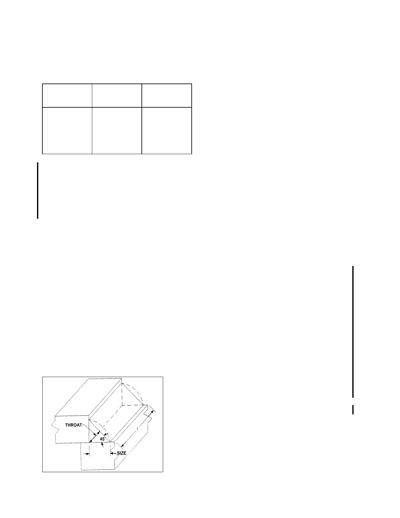
Lap welds are used in shear applications. The
weld throat of the fillet weld is considered the
plane 45 degrees to the surface plane of the
sheet being welded and is equal to 0.707 times
the thickness of the sheet stock. (See fig
ure 4-27.)
PWS =
where: PWS =
t =
l =
Fwsu =
0.707xtx1xFwsu
the allowable tensile
strength of the joint.
the thickness of the sheet
stock (the throat of the
weld joint.
the length of the weld joint.
the shear strength of the
filled rod material.
4-84. ROSETTE WELDS are generally
employed to fuse an inner reinforcing tube
(liner) with the outer member. Where a rosette
weld is used, drill a hole, (in the outside tube
only) of sufficient size to insure fusion of the
inner tube. A hole diameter of approximately
one-fourth the tube diameter of the outer tube
serves adequately for this purpose. In cases of
tight-fitting sleeves or inner liners, the rosettes
may be omitted. Rosette weld edge distance is
1/2 the diameter of the tube, as measured from
the edge of the rosette hole to the end of the
inside and outside tube. Rosettes shall not be
considered when determining the strength of a
welded form. Drill an 1/8-inch hole in the
lower tube in the center of the intended rosette
weld so the heat does not burn away the outer
tube. This small hole tends to bleed off the heat
from the torch and keeps the size of the rosette
small.
4-85. HEAT-TREATED
MEMBERS
Certain structural parts may be heat treated
and, therefore, could require special handling.
In general, the more responsive an alloy steel
is to heat treatment, the less suitable it is for
welding because of its tendency to become
brittle and lose its ductility in the welded area.
Weld the members which depend on heat
treatment for their original physical properties
by using a welding rod suitable for producing
heat-treated values comparable to those of the
original members. (See paragraph 4-74.) Af
ter welding, heat treat the affected members to
the manufacturer’s specifications.
4-86. TYPES OF WELDING.
a. Gas Welding. A fuel gas such as acety
lene or hydrogen is mixed inside a welding
torch with oxygen to produce a flame with a
temperature of around 6,300 °F (3,482 ºC).
FIGURE 4-27. Lap Weld Strength Calculation
Page 4-56
Par 4-75