FAA Advisory Circular 43.13-1B
Acceptable Methods, Techniques, and Practices
Aircraft Inspection and Repair
AC 43.13-1B | 4. Metal Structure, Welding, and Brazing | 5. Welding and Brazing | 4-103. Repairs to Welded Assemblies
AC 43.13-1B CHG 1
9/27/01
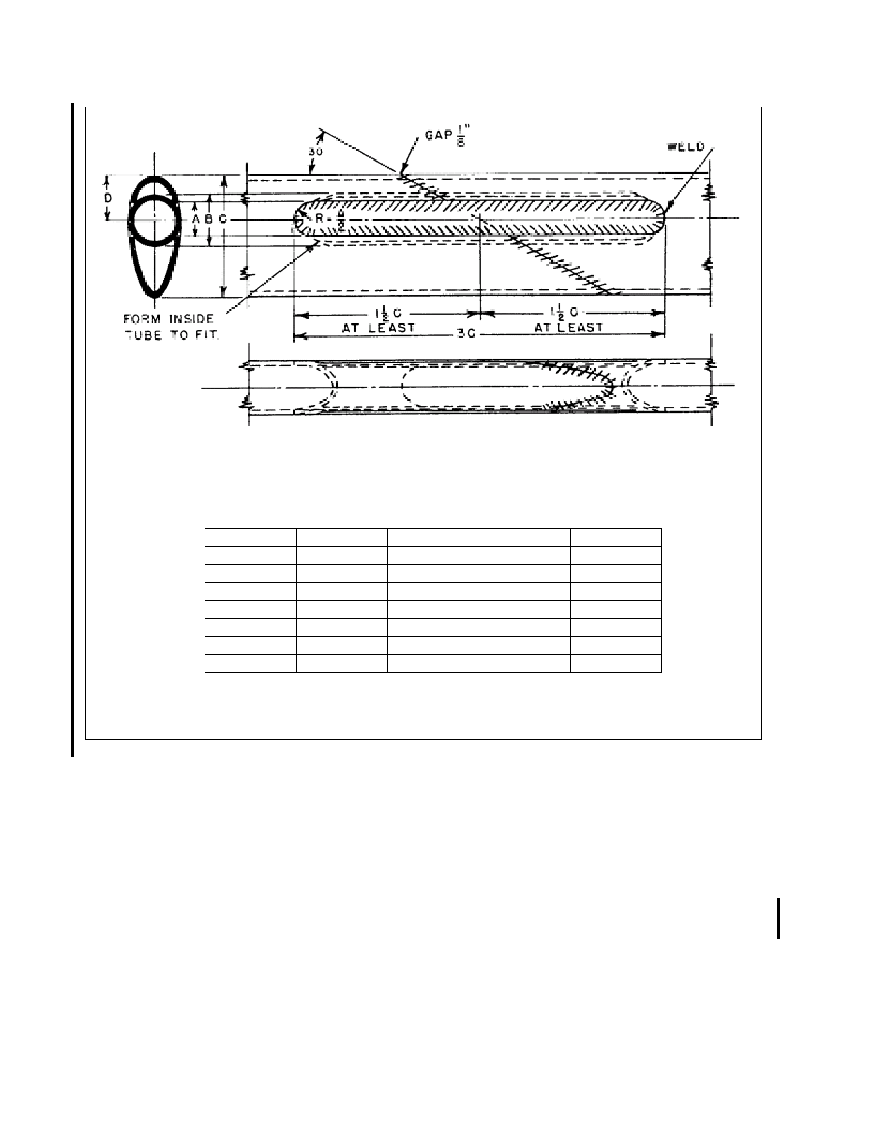
A- Slot Width (Original Tube).
B- Outside Diameter (Insert Tube).
C- Streamline Tube Length of Major Axis.
S.L. Size
A
1”
.375
1-¼
.375
1-½
.500
1-¾
.500
2
.500
2-¼
.500
2-½
.500
B
.563
.688
.875
1.000`
1.125
1.250
1.375
C
1.340
1.670
2.005
2.339
2.670
3.008
3.342
D
.496
.619
.743
.867
.991
1.115
1.239
ROUND INSERT TUBE (B) SHOULD BE AT LEAST OF SAME MATERIAL AND ONE GAUGE THICKER
THAN ORIGINAL STREAMLINE TUBE (C).
FIGURE 4-42. Streamline tube splice using round tube (applicable to landing gear).
d. shown in figure 4-35 through figure 4-45.
However, it will always be necessary to ascer
tain whether or not the members are heat
treated. The axle assembly as shown in fig
ure 4-47 is, in general, of a nonrepairable type
for the following reasons.
(1) The axle stub is usually made from a
highly heat-treated nickel alloy steel and care
fully machined to close tolerances. These
stubs are usually replaceable and must be re
placed if damaged.
(2) The oleo portion of the structure is gen
erally heat treated after welding, and is per
fectly machined to ensure proper functioning
of the shock absorber. These parts would be
distorted by welding after machining.
4-103. REPAIRS TO WELDED ASSEM
BLIES. These repairs may be made by the
following methods.
a. A welded joint may be repaired by cut
ting out the welded joint and replacing it with
one properly gusseted. Standard splicing pro
cedures should be followed.
Page 4-74
Par 4-102