FAA Advisory Circular 43.13-1B
Acceptable Methods, Techniques, and Practices
Aircraft Inspection and Repair
AC 43.13-1B | 4. Metal Structure, Welding, and Brazing | 5. Welding and Brazing | 4-104. Stainless Steel Structure
9/27/01
AC 43.13-1B CHG 1
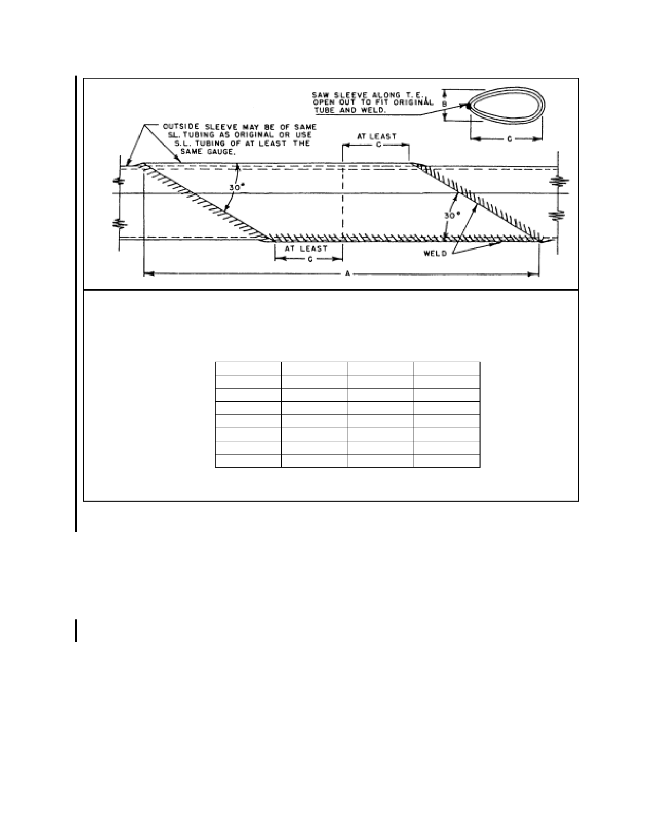
A- Minimum Length of Sleeve.
B- Streamline Tube Length of Minor Axis.
C- Streamline Tube Length of Major Axis.
S.L. Size
1”
1-¼
1-½
1-¾
2
2-¼
2-½
A
7.324
9.128
10.960
12.784
14.594
16.442
18.268
B
.572
.714
.858
1.000
1.144
1.286
1.430
C
1.340
1.670
2.005
2.339
2.670
3.008
3.342
FIGURE 4-43. Streamline tube splice using split sleeve (applicable to wing and tail surface brace struts and other
members).
b. Replacing weld deposit by chipping out
the metal deposited by the welding process and
rewelding after properly reinforcing the joint
by means of inserts or external gussets.
4-104. STAINLESS STEEL STRUC
TURE. Repair structural components made
from stainless steel, particularly the “18-8” va
riety (18 percent chromium, 8 percent nickel),
joined by spot welding, in accordance with the
instructions furnished by the manufacturer,
DER, or FAA. Substitution of bolted or riv
eted connections for spot-welded joints are to
be specifically approved by a DER or the
FAA. Repair secondary structural and non
structural elements such as tip bows or leading
and trailing edge tip strips of wing and control
surfaces by soldering with a 50-50 lead-tin sol
der or a 60-40 lead-tin solder. For best results,
use a flux of phosphoric acid (syrup). Since
the purpose of flux is to attack the metal so
that the soldering will be effective, remove ex
cess flux by washing the joint. Due to the
high-heat conductivity of the stainless steel,
use a soldering iron large enough to do the
work properly.
Par 4-103
Page 4-75