FAA Advisory Circular 43.13-1B
Acceptable Methods, Techniques, and Practices
Aircraft Inspection and Repair
AC 43.13-1B | 9. Aircraft Systems and Components | 2. Hydraulic Systems | 9-30. Hydraulic Lines and Fittings
9/27/01
AC 43.13-1B CHG 1
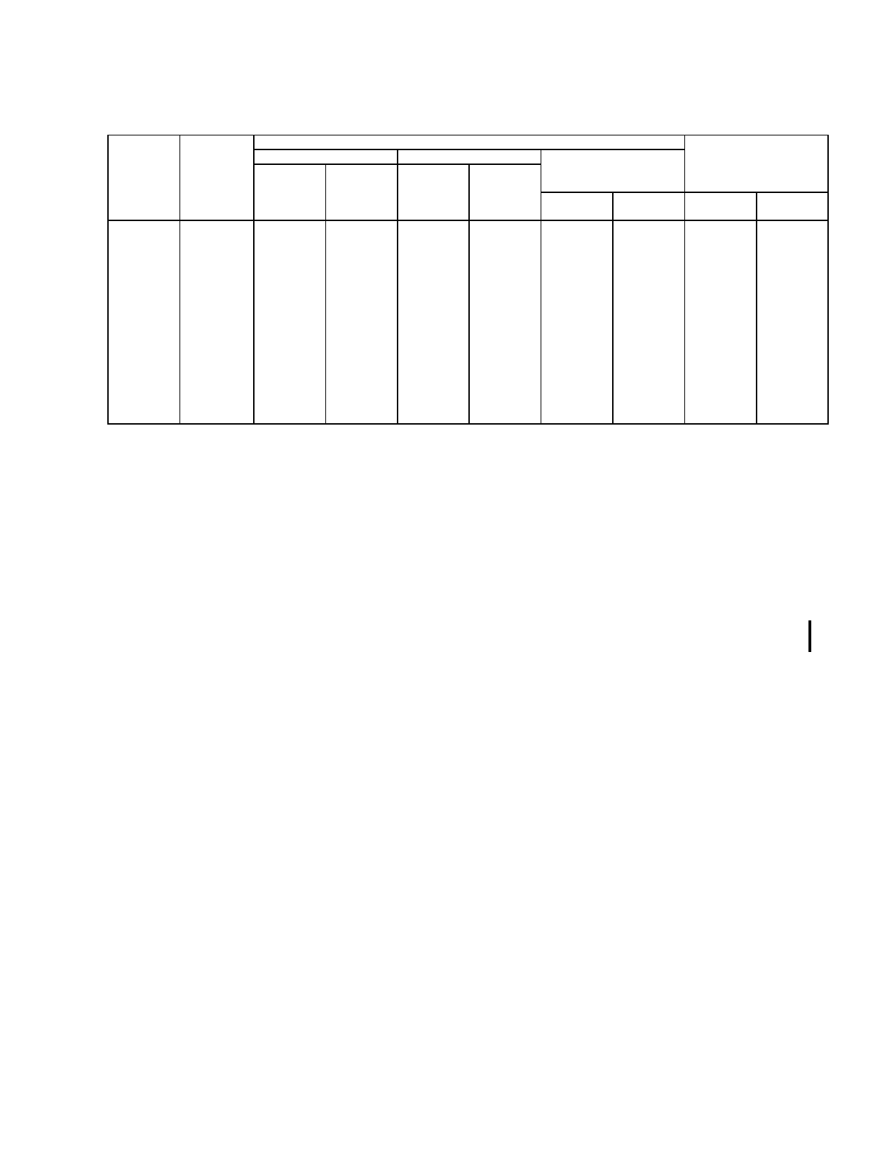
TABLE 9-2. Tube data.
Dash Nos.
Ref.
Tubing OD
inches
Wrench torque for tightening AN-818 Nut (pound inch)
Aluminum-alloy tubing
Steel tubing
Aluminum-alloy tubing
(Flare MS33583) for use
Minimum Maximum Minimum Maximum
on oxygen lines only
Minimum Maximum
-2
1/8
20
30
75
85
-
-
-3
3/16
25
35
95
105
-
-
-4
1/4
50
65
135
150
-
-
-5
5/16
70
90
170
200
100
125
-6
3/8
110
130
270
300
200
250
-8
1/2
230
260
450
500
300
400
-10
5/8
330
360
650
700
-
-
-12
3/4
460
500
900
1000
-
-
-16
1
500
700
1200
1400
-
-
-20
1-1/4
800
900
1520
1680
-
-
-24
1-1/2
800
900
1900
2100
-
-
-28
1-3/4
-
-
-
-
-
-
-32
2
1800
2000
2660
2940
-
-
Minimum bend radii
measured to tubing
centerline. Dimension
in inches.
Alum.
Steel
Alloy
3/8
7/16
9/16
3/4
15/16
1-1/4
1-1/2
1-3/4
3
3-3/4
5
-
8
-
21/32
7/8
1-1/8
1-5/16
1-3/4
2-3/16
2-5/8
3-1/2
4-3/8
5-1/4
-
7
d. Replacement of Flexible Lines. When
replacement of a flexible line is necessary, use
the same type, size, part number, and length of
hose as the line to be replaced. Check TSO
requirements. If the replacement of a hose
with a swaged-end type fitting is necessary,
obtain a new hose assembly of the correct size
and composition. Certain synthetic oils re
quire a specially compounded synthetic rubber
hose, which is compatible. Refer to the air
craft manufacturer’s service information for
the correct part number for the replacement
hose. If the fittings on each end are of the cor
rect type or sleeve type, a replacement may be
fabricated as shown in figure 9-8. Before cut
ting new flexible wire braided hose to the
proper size, tape the hose tightly with masking
tape and cut in the center of the masking tape
to prevent fraying. The use of a mandrel will
prevent cutting the inside of the hose when in
serting the fittings. Typical aircraft hose speci
fications and their uses are shown in table 9-3.
Install hose assemblies without twisting. (See
figure 9-9.) A hose should not be stretched
tight between two fittings as this will result in
overstressing and eventual failure. The length
of hose should be sufficient to provide about
5 to 8 percent slack. Avoid tight bends in flex
lines as they may result in
failure. Never exceed the minimum bend radii
as indicated in figure 9-10.
(1) Teflon hose is used in many aircraft
systems because it has superior qualities for
certain applications. Teflon is compounded
from tetrafluoroethylene resin which is unaf
fected by fluids normally used in aircraft. It
has an operating range of -65°F to 450 °F. For
these reasons, Teflon is used in hydraulic and
engine lubricating systems where temperatures
and pressures preclude the use of rubber hose.
Although Teflon hose has excellent perform
ance qualities, it also has peculiar characteris
tics that require extra care in handling. It tends
to assume a permanent set when exposed to
high pressure or temperature. Do not attempt
to straighten a hose that has been in service.
Any excessive bending or twisting may cause
kinking or weakening of the tubing wall. Re
place any hose that shows signs of leakage,
abrasion, or kinking. Any hose suspected of
kinking may be checked with a steel ball of
proper size. Table 9-4 shows hose and ball
sizes. The ball will not pass through if the
hose is distorted beyond limits.
(2) If the hose fittings are of the reus
able type, a replacement hose may be
Par 9-30
Page 9-19