FAA Advisory Circular 43.13-1B
Acceptable Methods, Techniques, and Practices
Aircraft Inspection and Repair
AC 43.13-1B | 8. Engines, Fuel, Exhaust, and Propellers | 4. Repair of Metal Propellers | 8-78. Deicing Systems
AC 43.13-1B
9/8/98
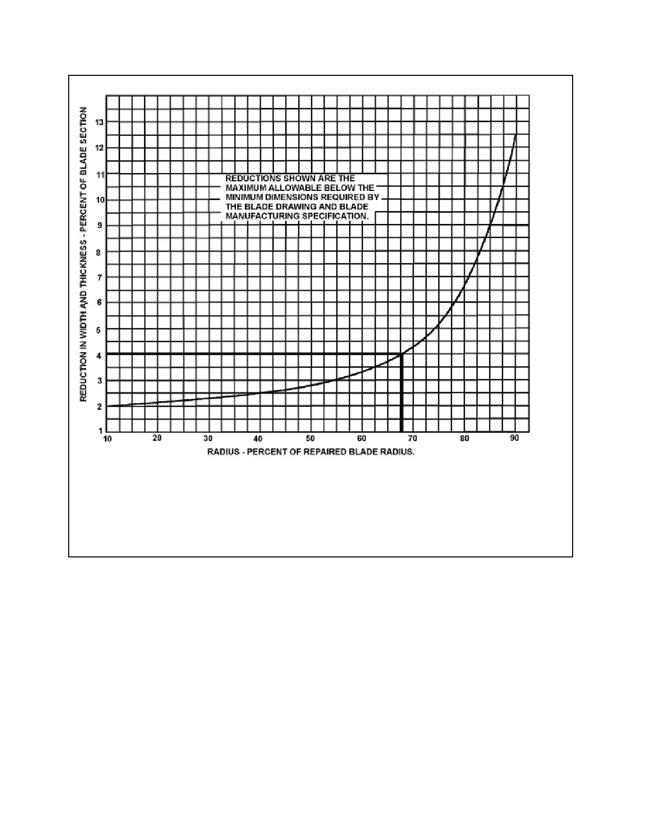
a. Draw a vertical line at the value of r% = 68 on the horizontal axis.
b. Where the vertical line intersects the curve, draw a horizontal line to the right to inter-
sect the vertical axis.
c. Read the percent reduction in thickness (∆t%) on the vertical axis intersection
∆t% = 4.0
FIGURE 8-28. Example 2. Determine the repair thickness limits.
method will always require the re-
drilling of all new propellers subse-
quently used with the re-drilled
flange.
8-77. CONTROL SYSTEMS. Components
used to control the operation of certificated
propellers should be inspected, repaired, as-
sembled, and/or tested in accordance with the
manufacturer’s recommendations. Only those
repairs which are covered by the manufac-
turer’s recommendations should be made, and
only those replacement parts which are ap-
proved under 14 CFR, part 21 should be used.
8-78. DEICING SYSTEMS. Components
used in propeller deicing systems should be in-
spected, repaired, assembled, and/or tested in
accordance with the manufacturer’s recom-
mendations. Only those repairs which are
covered by the manufacturer’s recommenda-
tions should be made, and only those replace-
ment parts which are approved under
14 CFR, part 21 should be used.
Page 8-34
Par 8-76