FAA Advisory Circular 43.13-1B
Acceptable Methods, Techniques, and Practices
Aircraft Inspection and Repair
AC 43.13-1B | 8. Engines, Fuel, Exhaust, and Propellers | 4. Repair of Metal Propellers | 8-74. Repair Limits
AC 43.13-1B
9/8/98
a. No repairs are permitted to the shanks
(roots or hub ends) of aluminum-alloy, adjust-
able-pitch blades. The shanks must be within
manufacturer’s limits.
b. The following two examples show
how to determine the allowable repair limits
on aluminum alloy blades.
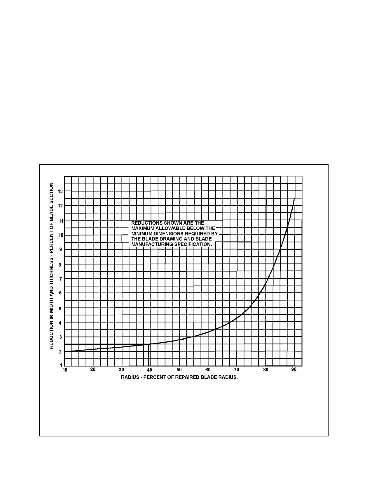
(r1) is 24 in. from the shank and the original,
as manufactured, blade width (w) at the repair
location is 1.88 in.
(a) Step 1. Calculate the blade radius
(r)
r = d/2 = (10 ft 6 in)/2 = 126/2 = 63 in.
(1) Example 1. Determine the blade
width repair allowable (∆w) and minimum
blade width limit, (w1) for a blade having a di-
ameter (d) of 10 ft. 6 in. The repair location
(b) Step 2. Calculate percent of
blade radius to repair (r%)
r% = r1/r x 100 = (24/63) x 100 = 38
a. Draw a vertical line at the value of r% = 38 on the horizontal axis.
b. Where the vertical line intersects the curve, draw a horizontal line to the right to
intersect the vertical axis.
c. Read the percent reduction in width (∆w%) on the vertical axis at this intersection.
∆w% = 2.5
FIGURE 8-27. Example 1. Determine the repair width limits.
Page 8-32
Par 8-74