FAA Advisory Circular 43.13-1B
Acceptable Methods, Techniques, and Practices
Aircraft Inspection and Repair
AC 43.13-1B | 5. Nondestructive Inspection (NDI) | 7. Ultrasonic Inspection | 5-94. Inspection of Bonded Structures
9/27/01
AC 43.13-1B CHG 1
or is a configuration that provides an ultrasonic
response pattern representative of the test
structure. The reference standard contains a
simulated defect (notch) that is positioned to
provide a calibration signal representative of
the expected defect. The notch size is chosen
to establish inspection sensitivity (response to
the expected defect size). The inspection pro-
cedure gives a detailed description of the re-
quired reference standard.
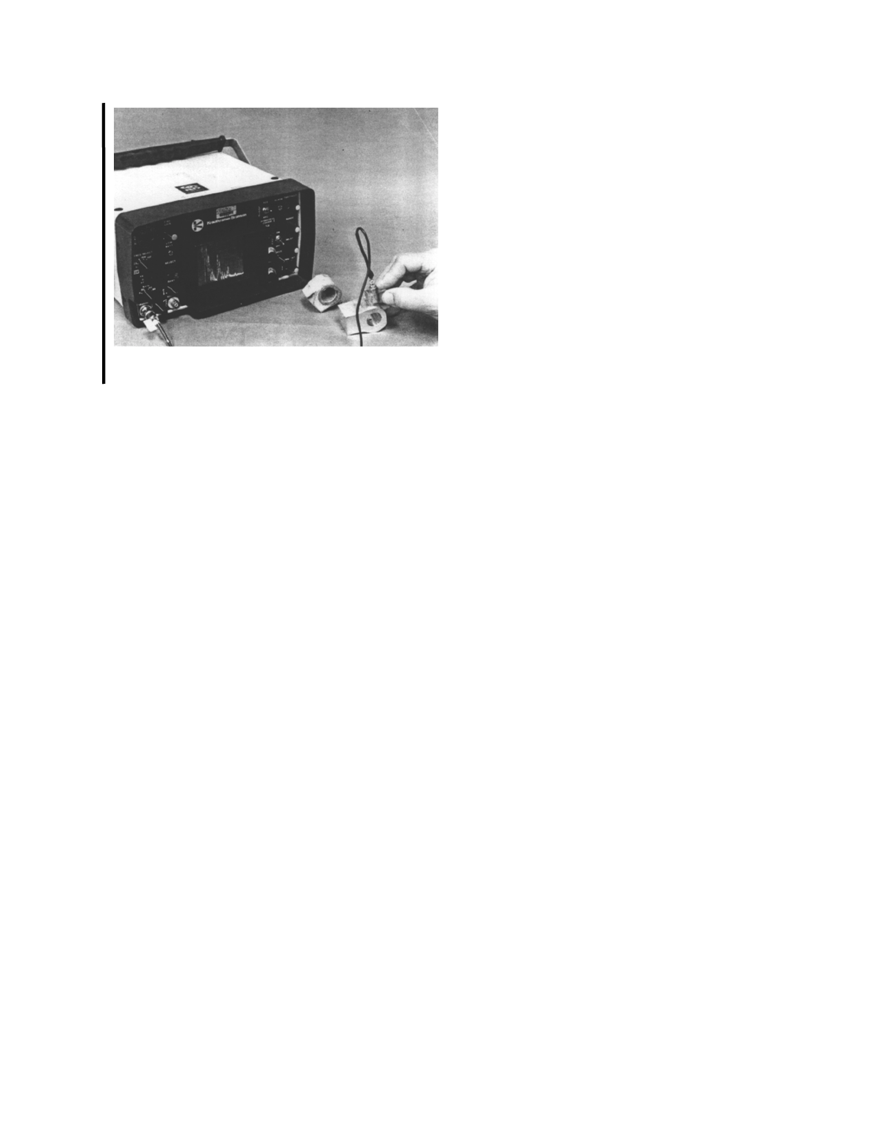
FIGURE 5-17. Typical portable ultrasonic inspection in-
strument.
ultrasonic pulse, detects and amplifies the re-
turning echo, and displays the detected signal
on a cathode ray tube or similar display. Pie-
zoelectric transducers produce longitudinal or
shear waves, which are the most commonly
used wave forms for aircraft structural inspec-
tion.
b. Positioning Fixtures. To direct ultra-
sound at a particular angle, or to couple it into
an irregular surface, transducer positioning
fixtures and sound-coupling shoes are em-
ployed. (See figure 5-18.) Shoes are made of
a plastic material that has the necessary sound-
transmitting characteristics. Positioning fix-
tures are used to locate the transducer at a pre-
scribed point and can increase the sensitivity
of the inspection. (See figure 5-19.) If a
transducer shoe or positioning fixture is re-
quired, the inspection procedure will give a
detailed description of the shoe or fixture.
c. Reference Standards. Reference stan-
dards are used to calibrate the ultrasonic in-
strument (see figure 5-20), reference standards
serve two purposes to provide an ultrasonic re-
sponse pattern that is related to the part being
inspected, and to establish the required inspec-
tion sensitivity. To obtain a representative re-
sponse pattern, the reference standard configu-
ration is the same as that of the test structure,
d. Couplants. Inspection with ultrasonics
is limited to the part in contact with the trans-
ducer. A layer of couplant is required to cou-
ple the transducer to the test piece because ul-
trasonic energy will not travel through air.
Some typical couplants used are: water, glyc-
erin, motor oils, and grease.
5-94. INSPECTION OF BONDED
STRUCTURES. Ultrasonic inspection is
finding increasing application in aircraft
bonded construction and repair. Detailed tech-
niques for specific bonded structures should be
obtained from the OEM’s manuals, or FAA re-
quirements. In addition, further information
on the operation of specific instruments should
be obtained from the applicable equipment
manufacturer manuals.
a. Types of Bonded Structures. Many
configurations and types of bonded structures
are in use in aircraft. All of these variations
complicate the application of ultrasonic in-
spections. An inspection method that works
well on one part or one area of the part may
not be applicable for different parts or areas of
the same part. Some of the variables in the
types of bonded structures are as follows.
(1) Top skin material is made from dif-
ferent materials and thickness.
(2) Different types and thickness of ad-
hesives are used in bonded structures.
Par 5-93
Page 5-43