FAA Advisory Circular 43.13-1B
Acceptable Methods, Techniques, and Practices
Aircraft Inspection and Repair
AC 43.13-1B | 5. Nondestructive Inspection (NDI) | 6. Radiography (X-Ray) Inspection | 5-80. Comparison with Other Ndi Methods
AC 43.13-1B
9/8/98
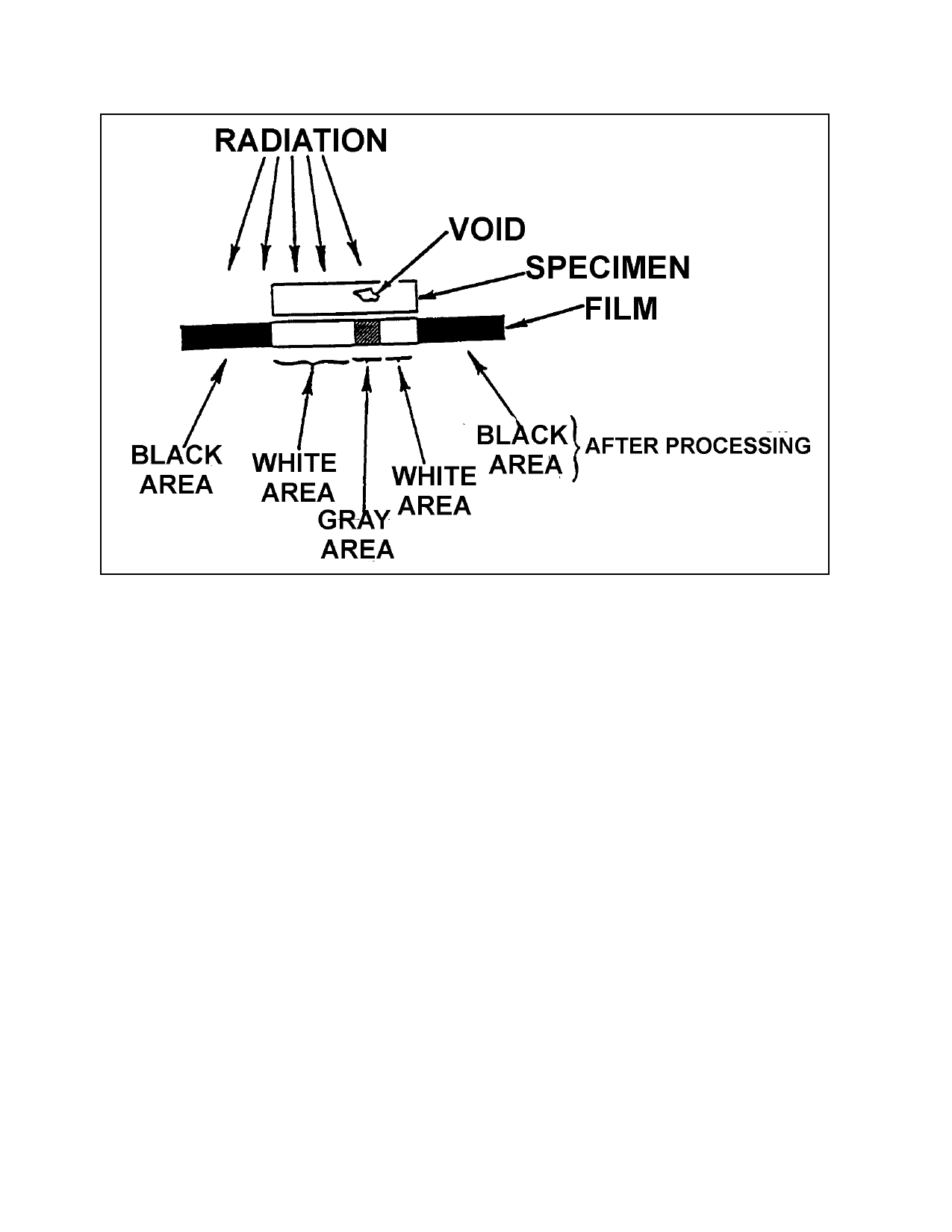
FIGURE 5-14. Radiography.
projection. The CT image is comparable to
that obtained by making a radiograph of a
physically sectioned thin planar slab from an
object. This cross-sectional image is not ob-
scured by overlying and underlying structures
and is highly sensitive to small differences in
relative density. Computed tomography im-
ages are also easier to interpret than radio-
graphs.
5-79. USES OF RADIOGRAPHY. Radi-
ography is used to detect the features of a
component or assembly that exhibit a differ-
ence in thickness or density as compared to
surrounding material. Large differences are
more easily detected than small ones. In gen-
eral, radiography can detect only those features
that have an appreciable thickness in a direc-
tion along the axis of the radiation beam.
Therefore, the ability of radiography to detect
planar discontinuities, such as cracks, depends
on proper orientation of the test piece during
inspection. Discontinuities which have
measurable thickness in all directions, such as
voids and inclusions, can be detected as long
as they are not too small in relation to section
thickness. In general, features that exhibit a
2 percent or more difference in radiation ad-
sorption compared to the surrounding material
can be detected.
5-80. COMPARISON WITH OTHER
NDI METHODS. Radiography and ultra-
sonic are the two generally-used, nondestruc-
tive inspection methods that can satisfactorily
detect flaws that are completely internal and
located well below the surface of the test part.
Neither method is limited to the detection of
specific types of internal flaws. However, ra-
diography is more effective when the flaws are
not planar, while ultrasonic is more effective
when flaws are planar. In comparison to other
generally-used NDI methods (e.g., magnetic
particle, liquid penetrant, and eddy current in-
spection), radiography has the following ad-
vantages.
Page 5-38
Par 5-78