FAA Advisory Circular 43.13-1B
Acceptable Methods, Techniques, and Practices
Aircraft Inspection and Repair
AC 43.13-1B | 5. Nondestructive Inspection (NDI) | 4. Magnetic Particle Inspection | 5-41. Principles of Operation
9/8/98
SECTION 4. MAGNETIC PARTICLE INSPECTION
AC 43.13-1B
5-40. GENERAL. Magnetic particle in-
spection is a method for detecting cracks, laps,
seams, voids, pits, subsurface holes, and other
surface, or slightly subsurface, discontinuities
in ferro-magnetic materials. Magnetic particle
inspection can be used only on ferro-magnetic
materials (iron and steel). It can be performed
on raw material, billets, finished and semi-
finished materials, welds, and in-service as-
sembled or disassembled parts. Magnetic par-
ticles are applied over a surface either dry, as a
powder, or wet, as particles in a liquid carrier
such as oil or water.
Common uses for magnetic particle inspection
are; final inspection, receiving inspection, in-
process inspection; and quality control, main-
tenance, and overhaul.
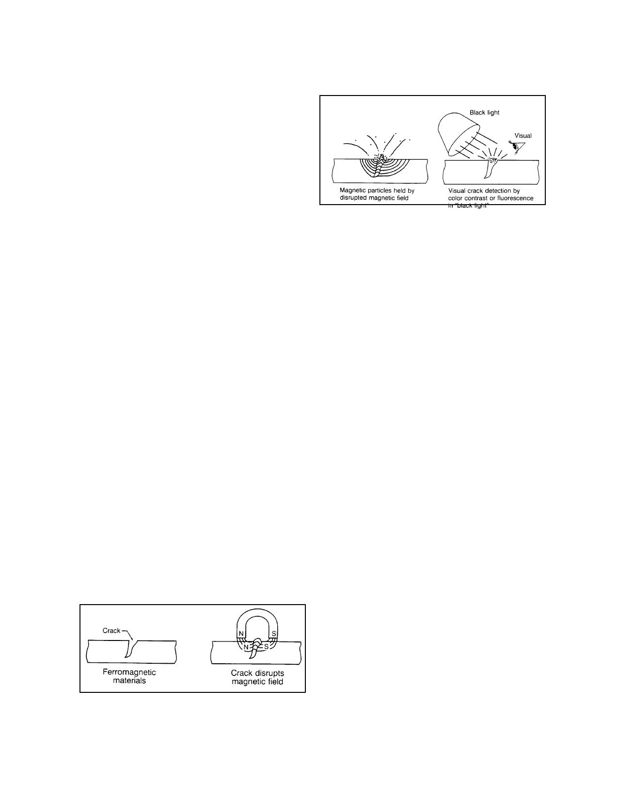
5-41. PRINCIPLES OF OPERATION.
Magnetic particle inspection uses the tendency
of magnetic lines of force, or flux, of an ap-
plied field to pass through the metal rather
than through the air. A defect at or near the
metal’s surface distorts the distribution of the
magnetic flux and some of the flux is forced to
pass out through the surface. (See figure 5-9.)
The field strength is increased in the area of
the defect and opposite magnetic poles form
on either side of the defect. Fine magnetic
particles applied to the part are attracted to
these regions and form a pattern around the de-
fect. The pattern of particles provides a visual
indication of a defect. (See figure 5-10.)
FIGURE 5-10. Crack detection by magnetic particle in-
spection.
a. To locate a defect, it is necessary to
control the direction of magnetization, and flux
lines must be perpendicular to the longitudinal
axes of expected defects. Examination of
critical areas for defects may require complete
disassembly. Two methods of magnetization,
circular and longitudinal, are used to magnet-
ize the part and induce perpendicular flux
paths. Parts of complex configuration may re-
quire local magnetization to ensure proper
magnetic field direction and adequate removal
of surface coatings, sealants, and other similar
compounds. Possible adverse influence of the
applied or residual magnetic fields on delicate
parts such as instruments, bearings, and
mechanisms may require removal of these
parts before performing the inspection.
b. Certain characteristics inherent in
the magnetic particle method may introduce
errors in examination results. Nonrelevant er-
rors are caused by magnetic field distortions
due to intentional design features, such as:
(1) Sharp radii, less than 0.10 inch ra-
dius, in fillets;
(2) Thread roots, keyways, and drilled
holes; and
FIGURE 5-9. Magnetic field disrupted.
(3) Abrupt changes in geometry or in
magnetic properties within the part.
Par 5-40
Page 5-19