FAA Advisory Circular 43.13-1B
Acceptable Methods, Techniques, and Practices
Aircraft Inspection and Repair
AC 43.13-1B | 3. Fiberglass and Plastics | 1. Repair of Light Load Laminate Structures | 3-3. Repairing Holes
9/8/98
AC 43.13-1B
be removed by either sanding with a power
sander or hand sanding with 180-grit
sandpaper.
(1) Scarf back the edges of the hole
about 50 times the thickness of the face ply.
Thoroughly clean out all of the sanding residue
with a cloth wet with an acceptable cleanser.
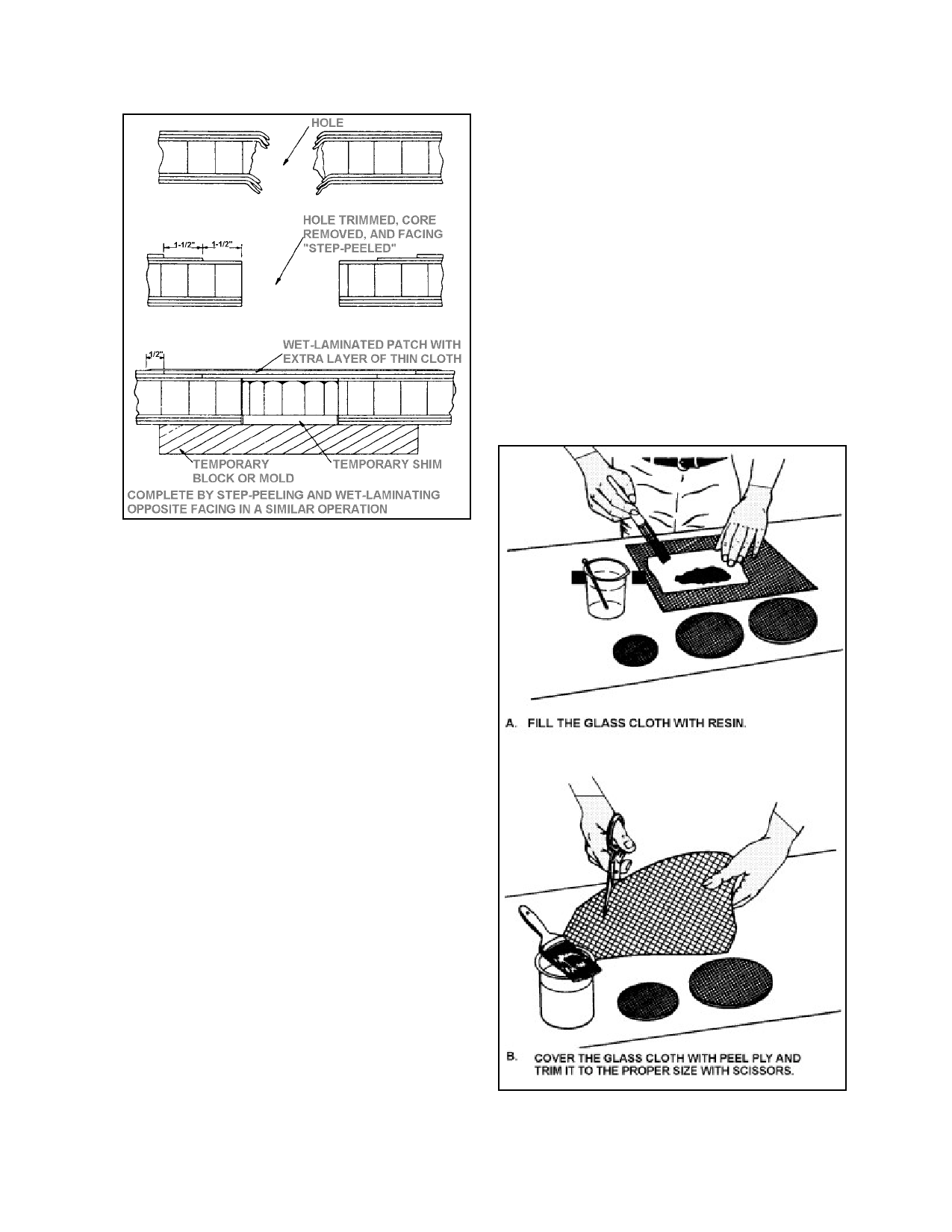
(2) Prepare the patches by (see fig
ure 3-4) laying the proper weight fiberglass
cloth impregnated with resin on a piece of peel
ply. A weight of resin equal to the weight of
the patch provides a 50-percent ratio.
FIGURE 3-3. Typical stepped joint repair.
c. Use replacement core stock of the
same material and density as the original (or an
acceptable substitute) and cut it to fit snugly in
the trimmed hole. Observe the direction of the
original core. When all of the pieces of re
placement facing laminations are cut and
soaked in resin, coat all surfaces of the hole
and the scarfed area with resin. Then coat all
surfaces of the core replacement with resin and
insert it into the hole. After all of the pieces of
resin-impregnated glass-fabric facing are in
place and lined up with the original fi
ber-orientation, cover the entire area with a
piece of peel ply and carefully work down the
layers of fabric to remove any air bubbles and
excess resin. Apply light pressure by means of
sand bags or a vacuum bag. When the resin
has cured, sand the repair to match the original
contour and refinish the surface.
3-3. REPAIRING HOLES.
a. Scarf Method. If the damaged area is
less than 3 inches in diameter, the damage may
FIGURE 3-4. Preparing the fiberglass sandwich.
Par 3-2
Page 3-3