FAA Advisory Circular 43.13-1B
Acceptable Methods, Techniques, and Practices
Aircraft Inspection and Repair
AC 43.13-1B | 11. Aircraft Electrical Systems | 19. Protection of Unused Connectors | 11-263. Pressurized Areas

AC 43.13-1B
9/8/98
TABLE 11-25. Contact cavity sealing-quick reference.
Connector Installation Types
Unpressurized Area
Sealing Means
Firewall
Non-Firewall
Sealing Plugs or
Teflon Sealing Rods
No
Yes
Stub Wires (Note 2)
Yes
No
Spare Contacts
Yes
Yes
NOTE 1: Sealing plugs may be included with the spare connector and may be used for sealing unused contacts.
ing rods are procured from stock by the foot. (See table 11-26 for sealing rod dimensions.)
Seal-
NOTE 2: Stub wires must be of the same type as the other wires of the bundle.
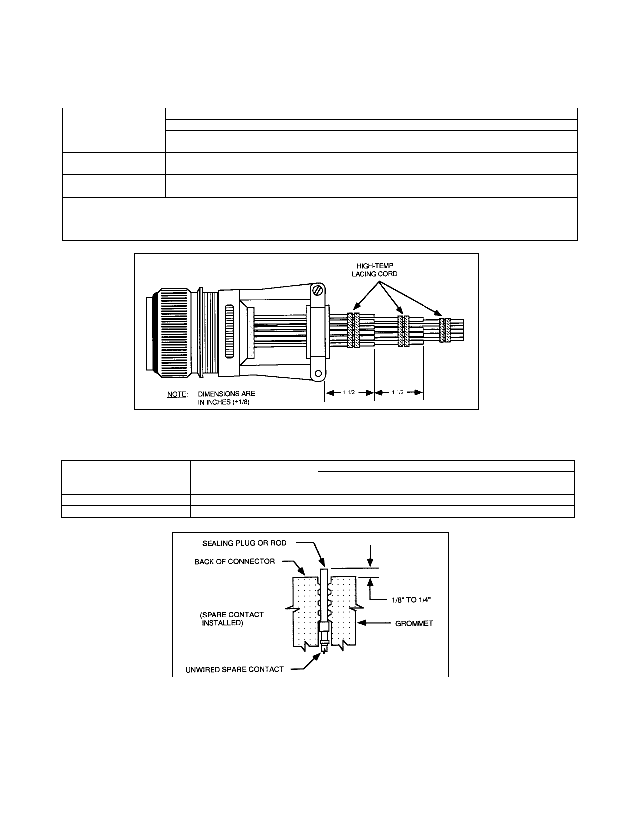
FIGURE 11-39. Stub wire installation.
TABLE 11-26. Sealing rod dimensions.
CONTACT SIZE
(AWG)
20
16
12
DIAMETER
(INCHES)
1/16
3/32
1/8
ROD LENGTH (INCHES)
MIN
MAX
5/8”
3/4”
7/8”
1”
7/8”
1”
FIGURE 11-40. Sealing unused contact cavities-unpressurized areas-(cut-away view).
11-264.11-270. [RESERVED.]
Page 11-104
Par 11-263