FAA Advisory Circular 43.13-1B
Acceptable Methods, Techniques, and Practices
Aircraft Inspection and Repair
AC 43.13-1B | 1. Wood Structure | 4. Repairs | 1-46. Rib Repairs

9/8/98
AC 43.13-1B
Section A-A
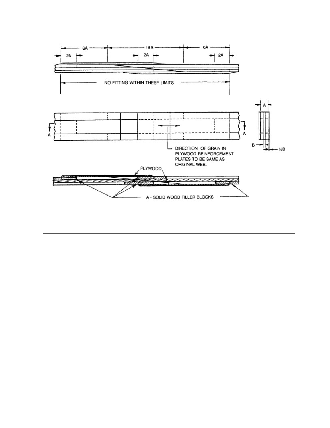
FIGURE 1-7. Repairs to built-up “I” spar.
Ends of reinforcement plates
should be feathered out
with a 5:1 slope.
a. Rib Repair Methods. Acceptable
methods of repairing damaged ribs are shown
in figure 1-11. Wood ribs should not be nailed
to wood spars by driving nails through the rib
cap strips, as this weakens the rib materially.
The attachment should be by means of adhe-
sive with cement coated, barbed, or spiraled
nails driven through the vertical rib members
on each face of the spar.
assumed to be cracked through the cap strips,
web member, and compression member in the
illustration. Cut the compression member as
shown in figure 1-12(D). Cut and replace the
aft portion of the cap strips, and reinforce as
shown in figure 1-11. The plywood side plates
are bonded on, as indicated in figure 1-12(A).
These plates are added to reinforce the dam-
aged web.
b. Compression Rib Repair. Acceptable
methods of repairing damaged compression
ribs are shown in figure 1-12.
(1) Figure 1-12(A) illustrates the repair
of a compression rib of the “I” section type;
i.e., wide, shallow cap strips, and a center ply-
wood web with a rectangular compression
member on each side of the web. The rib is
(2) Figure 1-12(B) illustrates a com-
pression rib of the type that is basically a stan-
dard rib with rectangular compression mem-
bers added to one side and plywood web to the
other side. The method used in this repair is
essentially the same as in figure 1-12(A) ex-
cept that the plywood reinforcement plate,
Par 1-46
Page 1-19