FAA Advisory Circular 43.13-1B
Acceptable Methods, Techniques, and Practices
Aircraft Inspection and Repair
AC 43.13-1B | 1. Wood Structure | 4. Repairs | 1-40. Splicing of Spars
9/8/98
SECTION 4. REPAIRS
AC 43.13-1B
1-36. GENERAL. The basic standard for
any aircraft repair is that the repaired structure
must be as strong as the original structure and
be equivalent to the original in rigidity and
aerodynamic shape. Repairs should be made
in accordance with manufacturer specifications
whenever such data is available.
both parts accurately. The strength of the
joints depends upon good joint design and a
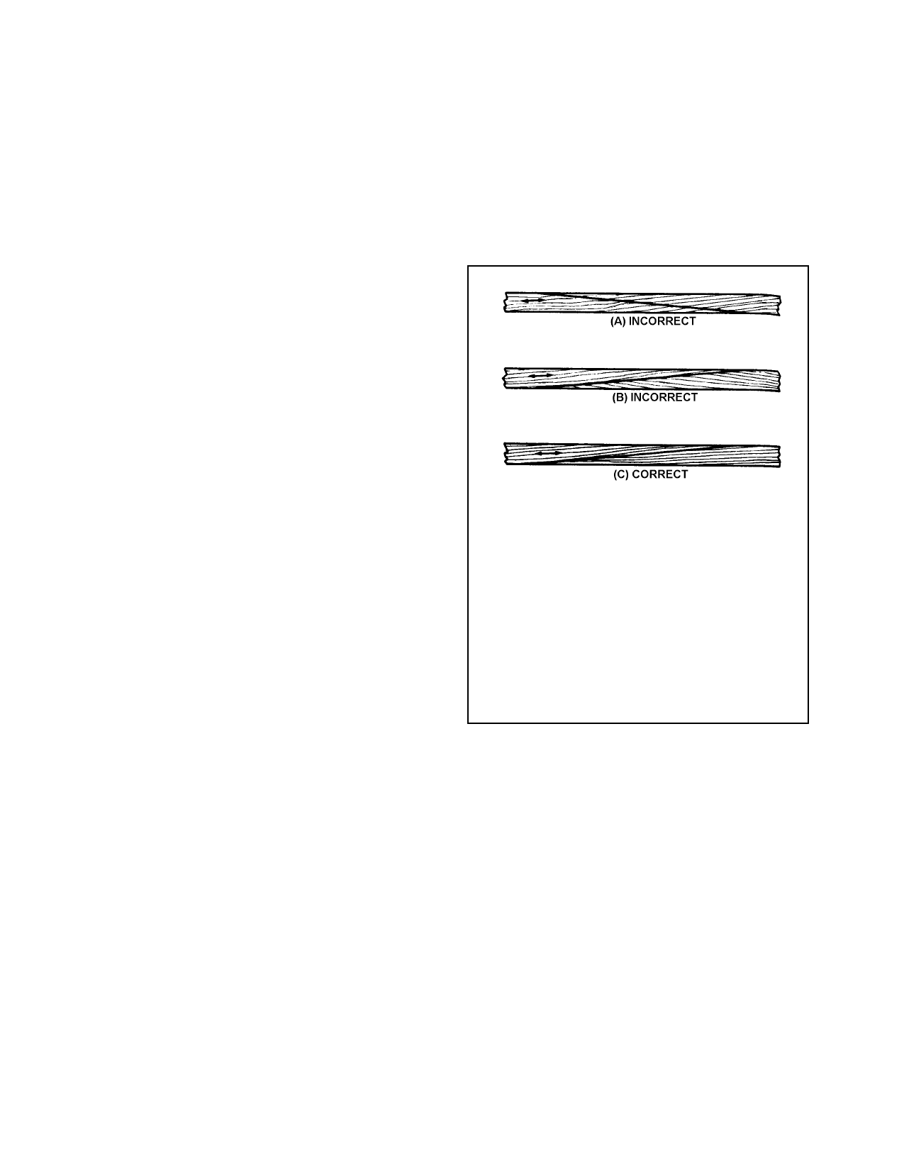
thin, uniform bond line. Make the scarf cut in
the general direction of the grain slope as
shown in figure 1-4.
1-37. REPLACEMENT OF DRAIN
HOLES AND SKIN STIFFENERS. When-
ever repairs are made that require replacing a
portion that includes drain holes, skin stiffen-
ers, or any other items, the repaired portion
must be provided with similar drain holes, skin
stiffeners, or items of the same dimensions in
the same location. Additional drain holes may
be required if reinforcement under a skin re-
pair interferes with waterflow to existing drain
holes. Make any additional drain holes the
same diameter as originals, usually 1/4 inch.
1-38. CONTROL SURFACE FLUTTER
PRECAUTIONS. When repairing or refin-
ishing control surfaces, especially on high-
performance airplanes, care must be exercised
that the repairs do not involve the addition of
weight aft of the hinge line. Such a procedure
may adversely affect the balance of the surface
to a degree that could induce flutter. As a gen-
eral rule, it will be necessary to repair control
surfaces in such a manner that the structure is
identical to the original, and that the stiffness,
weight distribution, and mass balance are not
affected in any way. Consult the aircraft
maintenance manual or seek manufacturer’s
direction for specific requirements on checking
control surface balance after repair and refin-
ishing of any control surface.
1-39. SCARF JOINTS. The scarf joint is
the most satisfactory method of making an end
joint between two solid wood members. Cut
No grain deviation steeper than
1 in 15 should be present in an outer
eighth of the depth of the spar. In
adjacent eighths, deviations involving
steeper slopes, such as a wave in a
few growth layers, are unlikely to be
harmful. Local grain slope deviations
in excess of those specified may be
permitted in spar flanges only in the
inner one-fourth of the flange depth.
FIGURE 1-4. Consideration of grain direction when
making scarf joints.
1-40. SPLICING OF SPARS. Unless oth-
erwise specified by the manufacturer, a spar
may be spliced at any point except under the
wing attachment fittings, landing gear fittings,
engine mount fittings, or lift and interplane
strut fittings. These fittings may not overlap
any part of the splice. A spar splice repair
should not be made adjacent to a previous
splice or adjacent to a reinforcing plate.
Spacing between two splices or between a
splice and a reinforcing plate should be no less
than three times the length of the longer splice.
Par 1-36
Page 1-15