FAA Advisory Circular 43.13-1B
Acceptable Methods, Techniques, and Practices
Aircraft Inspection and Repair
AC 43.13-1B | 8. Engines, Fuel, Exhaust, and Propellers | 2. Fuel Systems | 8-31. Fuel Lines and Fittings
9/8/98
SECTION 2. FUEL SYSTEMS
AC 43.13-1B
8-30. GENERAL. Maintain, service, and
adjust aircraft fuel systems and fuel system
components in accordance with the applicable
manufacturer’s maintenance instructions.
Certain general fuel system maintenance prin-
ciples are outlined in the following para-
graphs..
8-31. FUEL LINES AND FITTINGS.
When fuel system lines are to be replaced or
repaired, consider the following fundamentals
in addition to the applicable airworthiness re-
quirements. Additional inspection and repair
practices for aircraft tubing systems may be
found in the Chapter 9, Aircraft Systems and
Components.
a. Compatibility of Fittings. All fittings
are to be compatible with their mating parts.
Although various types of fittings appear to be
interchangeable in many cases they have dif-
ferent thread pitch or minor design differences
which prevent proper mating and may cause
the joint to leak or fail.
b. Routing. Make sure that the line does
not chafe against control cables, airframe
structure, etc., or come in contact with electri-
cal wiring or conduit. Where physical separa-
tion of the fuel lines from electrical wiring or
conduit is impracticable, locate the fuel line
below the wiring and clamp it securely to the
airframe structure. In no case should wiring be
supported by the fuel line.
c. Alignment. Locate bends accurately so
that the tubing is aligned with all support
clamps and end fittings and is not drawn,
pulled, or otherwise forced into place by them.
Never install a straight length of tubing be-
tween two rigidly-mounted fittings. Always
incorporate at least one bend between such fit-
tings to absorb strain caused by vibration and
temperature changes.
d. Bonding. Bond metallic fuel lines at
each point where they are clamped to the
structure. Integrally bonded and cushioned
line support clamps are preferred to other
clamping and bonding methods.
e. Support of Line Units. To prevent
possible failure, all fittings heavy enough to
cause the line to sag should be supported by
means other than the tubing.
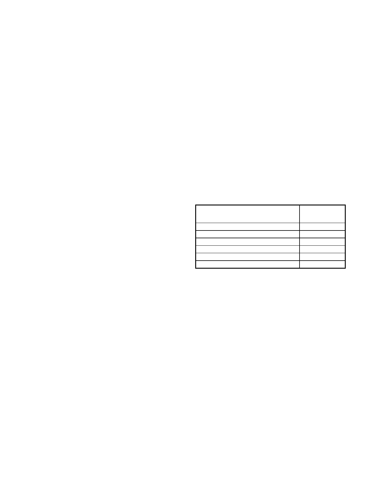
f. Support clamps.
(1) Place support clamps or brackets for
metallic lines as follows.
Tube O.D.
1/8”-3/16”---------------------------------
1/4”-5/16”---------------------------------
3/8”-1/2”-----------------------------------
5/8”-3/4”-----------------------------------
1”-1 1/4”-----------------------------------
1 1/2”-2”-----------------------------------
Approximate
distance between
supports
9”
12”
16”
22”
30”
40”
(2) Locate clamps or brackets as close
to bends as possible to reduce overhang. (See
figure 8-12.)
8-32. FUEL TANKS AND CELLS.
Welded or riveted fuel tanks that are made of
commercially pure aluminum, 3003, 5052, or
similar alloys, may be repaired by welding.
Tanks made from heat-treatable aluminum al-
loys are generally assembled by riveting. In
case it is necessary to rivet a new piece in a
tank, use the same material as used in the tank
undergoing repair, and seal the seams with a
compound that is insoluble in gasoline. Spe-
cial sealing compounds are available and
should be used in the repair of tanks. Inspect
fuel tanks and cells for general condition, secu-
rity of attachment, and evidence of leakage.
Examine fuel tank or cell vent line, fuel line,
and sump drain attachment fittings closely.
Par 8-30
Page 8-19