FAA Advisory Circular 43.13-1B
Acceptable Methods, Techniques, and Practices
Aircraft Inspection and Repair
AC 43.13-1B | 7. Aircraft Hardware, Control Cables, and Turnbuckles | 9. Turnbuckles | 7-166. Turnbuckle Installation
9/8/98
SECTION 9. TURNBUCKLES
AC 43.13-1B
7-165. GENERAL. A turnbuckle is a de-
vice used in cable systems to provide a means
of adjusting tension. Turnbuckles have barrel-
shaped sleeves with internal left- and right-
hand threads at opposite ends. The cables,
with terminals attached, are made to such a
length that, when the turnbuckle is adjusted to
give the specified cable tension, a sufficient
number of threads on the terminal ends are
screwed into the barrel to hold the load. The
clip-locking turnbuckle and its associated parts
are identical to standard AN and MS parts ex-
cept for a slot grooved on the interior of the
barrel and the shanks of the forks, eyes, etc.
The clip-locking turnbuckle parts have the
following drawing numbers: MS21251, turn-
buckle body; MS21252, turnbuckle clevis end;
MS21253, turnbuckle clevis end (for bearing);
NAS649 and NAS651, turnbuckle clip;
MS21254 and NAS648, turnbuckle eye (for
pin); MS21255 and NAS647, turnbuckle eye
end (for wire rope); NAS645 and NAS646,
turnbuckle fork; MS21256, turnbuckle barrel
locking clip; AN130-170, turnbuckle assem-
blies; and, MS21259 and MS21260, terminal,
wire rope, stud.
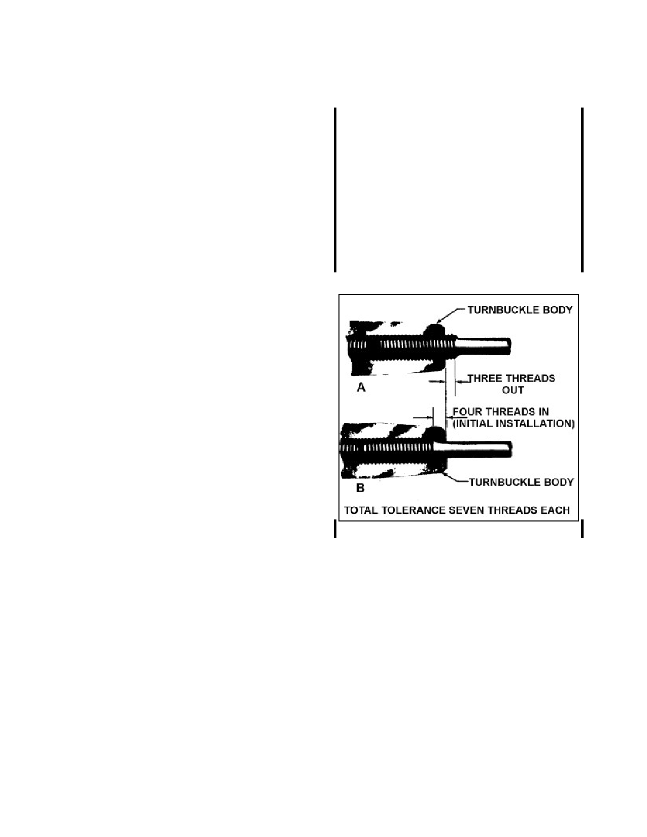
7-166. TURNBUCKLE INSTALLATION.
(See figure 7-25.) When installing cable sys-
tem turnbuckles, it is necessary to screw both
threaded terminals into the turnbuckle barrel
an equal amount. It is essential that turnbuckle
terminals be screwed into the barrel so that not
more than three threads on the terminal are ex-
posed. (See figure 7-23A.) On initial installa-
tion, the turnbuckle terminals should not be
screwed inside the turnbuckle barrel more than
four threads. (See figure 7-23B.)
NOTE: Turnbuckles showing signs of
thread distortion/bending should be
replaced. Turnbuckle ends are de-
signed for providing the specified ca-
ble tension on a cable system, and a
bent turnbuckle would place undesir-
able stress on the cable, impairing the
function of the turnbuckle.
FIGURE 7-25. Turnbuckle thread tolerance.
7-167. WITNESS HOLE. Some manufac-
turers of turnbuckles incorporate a “witness
hole,” in the turnbuckle barrel to ensure that
the threaded cable terminals are screwed in far
enough into the barrel. The “witness hole” can
be inspected visually, or by using a piece of
safety wire as a probe.
7-168.7-178. [RESERVED.]
Par 7-165
Page 7-41 (and 7-42)