FAA Advisory Circular 43.13-1B
Acceptable Methods, Techniques, and Practices
Aircraft Inspection and Repair
AC 43.13-1B | 7. Aircraft Hardware, Control Cables, and Turnbuckles | 8. Inspection and Repair of Control Cables and Turnbuckles | 7-151. Wire Splices
9/27/01
AC 43.13-1B CHG 1
FIGURE 7-21. Corrosion.
7-152. CABLE MAINTENANCE. Fre
quent inspections and preservation measures
such as rust-prevention treatments for bare
carbon steel cable areas, will help to extend
cable service life. Where cables pass through
fair-leads, pressure seals, or over pulleys, re
move accumulated heavy coatings of corro
sion-prevention compound. Provide corrosion
protection for these cable sections by lubricat
ing with a light coat of grease or general-
purpose, low-temperature oil.
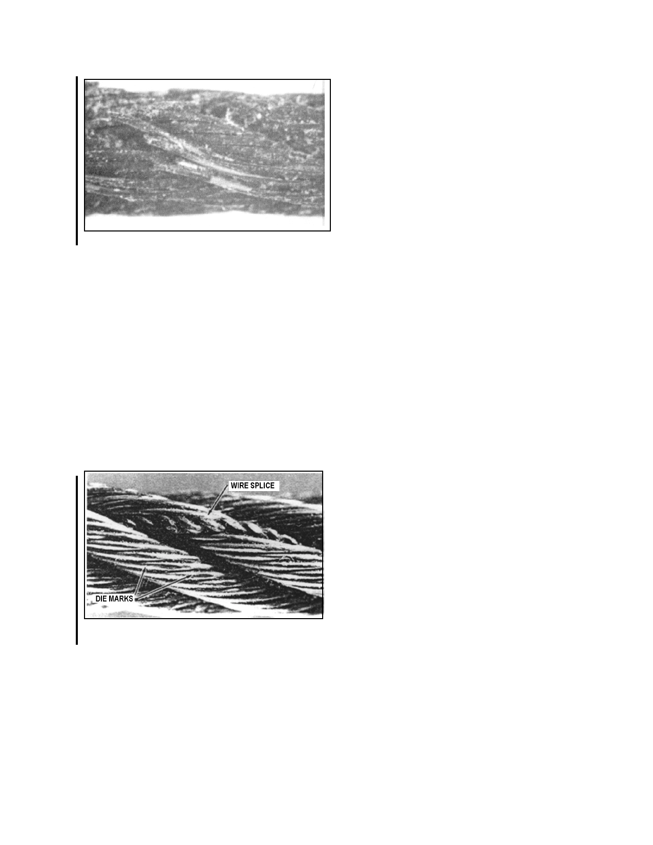
7-151. WIRE SPLICES. Standard manu
facturing splices have been mistaken for de
fects in the cable because individual wire end
splices were visible after assembly of a fin
ished cable length. In some instances, the pro
cess of twisting outer strands around the core
strand may also slightly flatten individual outer
wires, particularly in the area of a wire splice.
This flattening is the result of die-sizing the
cable, and does not affect the strength of the
cable. These conditions (as shown in fig
ure 7-22) are normal, and are not a cause for
cable rejection.
7-153. CABLE TENSION ADJUST-
MENT. Carefully adjust, control cable tension
in accordance with the airframe manufacturer’s
recommendations. On large aircraft, take the
temperature of the immediate area into consid
eration when using a tension meter. For long
cable sections, use the average of two or three
temperature readings to obtain accurate tension
values. If necessary, compensate for extreme
surface temperature variations that may be en
countered if the aircraft is operated primarily
in unusual geographic or climatic conditions
such as arctic, arid, or tropic locations. Use
rigging pins and gust locks, as necessary, to en
sure satisfactory results. At the completion of
rigging operations, check turnbuckle adjustment
and safetying in accordance with section 10 of
this chapter.
7-154.7-164. [RESERVED.]
FIGURE 7-22. Manufacturer’s wire splice.
Par 7-151
Page 7-39 (and 7-40)