FAA Advisory Circular 43.13-1B
Acceptable Methods, Techniques, and Practices
Aircraft Inspection and Repair
AC 43.13-1B | 7. Aircraft Hardware, Control Cables, and Turnbuckles | 8. Inspection and Repair of Control Cables and Turnbuckles | 7-146. Cable Proof Loads
9/8/98
AC 43.13-1B
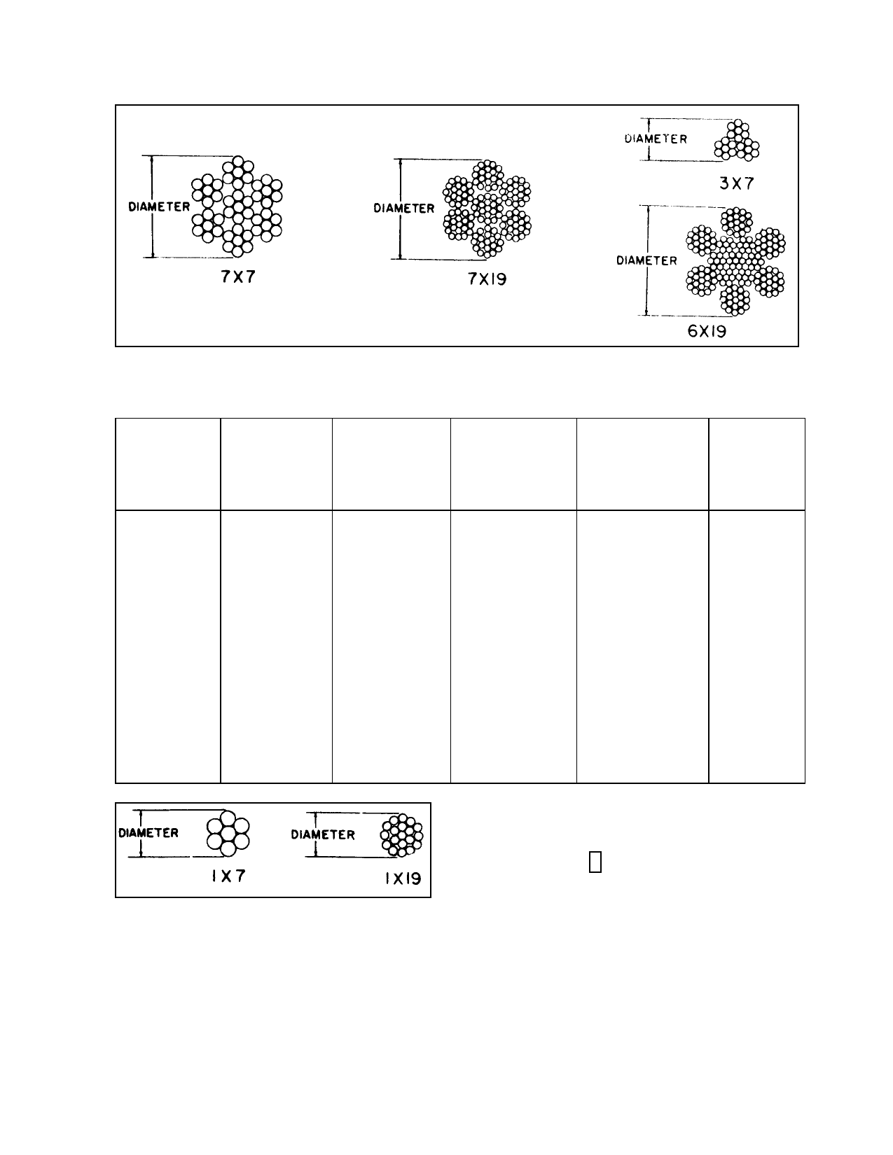
FIGURE 7-8. Flexible cable cross section.
TABLE 7-4. Nonflexible cable construction and physical properties.
STRAND
TYPE
I
I
II
I
II
II
II
II
II
II
II
II
II
II
II
NOMINAL
DIAMETER
OF
WIRE
STRAND
In.
1/32
3/64
3/64
1/16
1/16
5/64
3/32
7/64
1/8
5/32
3/16
7/32
1/4
5/16
3/8
TOLERANCE
ON
DIAMETER
(Plus Only)
In.
0.003
0.005
0.005
0.006
0.006
0.008
0.009
0.009
0.013
0.013
0.013
0.015
0.018
0.022
0.026
ALLOWABLE
INCREASE
IN
DIAMETER
AT THE END
In.
0.006
0.008
0.008
0.009
0.009
0.009
0.010
0.010
0.011
0.016
0.019
0.020
0.021
0.024
0.027
CONSTRUCTION
1 x 7
1 x 7
1 x 19
1 x 7
1 x 19
1 x 19
1 x 19
1 x 19
1 x 19
1 x 19
1 x 19
1 x 19
1 x 19
1 x 19
1 x 19
MIL-W-87161
MINIMUM
BREAK
STRENGTH
COMP A & B
Lbs.
185
375
375
500
500
800
1,200
1,600
2,100
3,300
4,700
6,300
8,200
12,500
17,500
FIGURE 7-9. Nonflexible cable cross section.
wires laid around a center wire in a counter
clockwise direction. The 1 by 19 cable con
sists of a layer of six wires laid around a center
wire in a clockwise direction plus twelve wires
laid around the inner strand in a counterclock
wise direction.
7-145. CABLE SPECIFICATIONS. Cable
diameter and strength data are given in ta
ble 7-3 and table 7-4. These values are accept
able for repair and modification of civil air
craft.
7-146. CABLE PROOF LOADS. Cable
terminals and splices should be tested for
proper strength before installation. Gradually
apply a test load equal to 60 percent of the ca
ble-breaking strengths given in table 7-3 and
Par 7-144
Page 7-29