FAA Advisory Circular 43.13-1B
Acceptable Methods, Techniques, and Practices
Aircraft Inspection and Repair
AC 43.13-1B | 4. Metal Structure, Welding, and Brazing | 5. Welding and Brazing | 4-80. Nondestructive Testing
9/27/01
roll over, cold lab, or unfued weld metal.
Check underside of welded joint for defects.
TABLE 4-12. Current and polarity selection for inert gas welding.
ALTERNATING
CURRENT
With High-
MATERIAL
Frequency
Stabilization
Magnesium up to ¹/8 in. thick..................................................
1
Magnesium above ³/16 in. thick...............................................
1
Magnesium Castings................................................................
1
Aluminum up to ³/32 in. thick..................................................
1
Aluminum over ³/32 in. thick ...................................................
1
Aluminum Castings .................................................................
1
Stainless Steel ..........................................................................
Low Carbon Steel, 0.015 to 0.030 in. .....................................
Low Carbon Steel, 0.030 to 0.125 in. .....................................
N.R.
1 Recommended
N.R. Not Recommended
AC 43.13-1B CHG 1
DIRECT
CURRENT
STRAIGHT
Polarity
N.R.
N.R.
N.R.
N.R.
N.R.
N.R.
1
1
1
4-79. MICROFISSURES Cracks in parts
and materials can vary from tiny microfissures,
that are visible only with magnification, to
those easily identified by unaided eyes. Micro-
fissures are the worst type of defect for two
reasons; they are often hard to detect, and they
produce the worst form of notch effect/stress
concentration. Once they form, they propagate
with repeated applications of stress and lead to
early failures. Every possible means should be
used to detect the presence of cracks, and en
sure their complete removal before welding
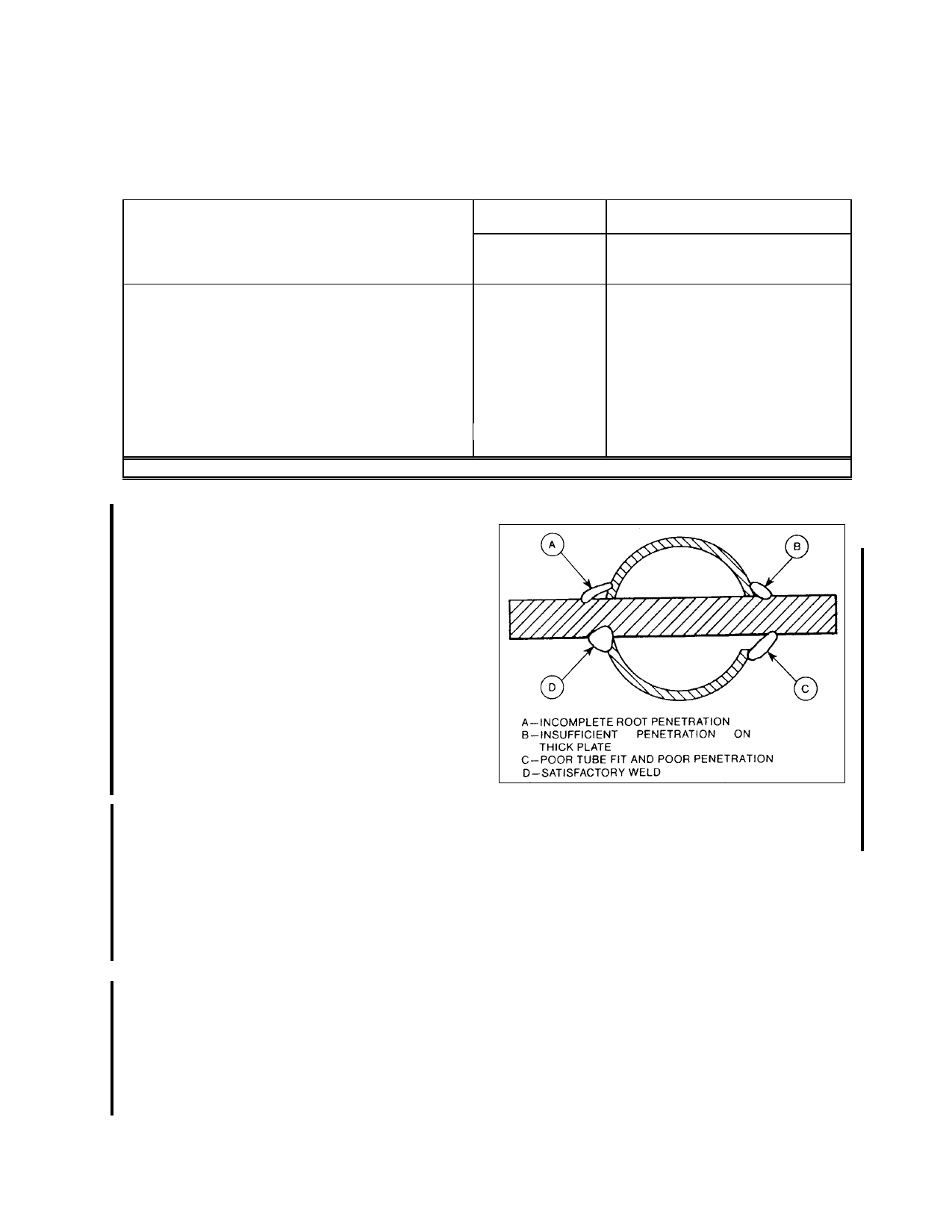
operations proceed. (See figure 4-26.)
4-80. NONDESTRUCTIVE TESTING or
evaluation is advisable in critical applications.
Nondestructive testing methods such as; mag
netic particle, liquid penetrant, radiography,
ultrasonic, eddy current, and acoustic emission
can be used; however, they require trained and
qualified people to apply them.
4-81. PRACTICES TO GUARD
AGAINST Do not file or grind welds in an
effort to create a smooth appearance, as such
treatment causes a loss of strength. Do not fill
welds with solder, brazing metal, or any other
filler. When it is necessary to weld a
FIGURE 4-26. Common defects to avoid when fitting
and welding aircraft certification cluster.
joint which was previously welded, remove all
of the old weld material before rewelding.
Avoid welding over a weld, because reheating
may cause the material to lose its strength and
become brittle. Never weld a joint which has
been previously brazed.
4-82. TORCH SIZE (Oxyacetylene weld
ing). When using oxyacetylene welding, the
torch tip size depends upon the thickness of
the material to be welded. Commonly used
Par 4-78
Page 4-55