FAA Advisory Circular 43.13-1B
Acceptable Methods, Techniques, and Practices
Aircraft Inspection and Repair
AC 43.13-1B | 12. Aircraft Avionics Systems | 4. Pitot/Static System | 12-54. Static Ports
9/27/01
AC 43.13-1B CHG 1
SECTION 4. PITOT/STATIC SYSTEMS
12-51. GENERAL. In order for the pitot
static instruments to work properly, they must
be connected into a system that senses the im
pact air pressure with minimum distortion and
picks up undisturbed static air pressure.
Pitot pressure is ram air pressure picked up by
a small open-ended tube about a ¼-inch in di
ameter that sticks directly into the air stream
that produces a pressure proportional to the
speed of the air movement. Static pressure is
the pressure of the still air used to measure the
altitude and serves as a reference in the meas
urement of airspeed.
12-53. PITOT/STATIC TUBES AND
LINES. The pitot tube (see figure 12-6) is in
stalled at the leading edge of the wing of a sin
gle-engine aircraft, outside the propeller slip
stream or on the fuselage of a multiengine air
craft with the axis parallel to the longitudinal
axis of the aircraft, unless otherwise specified
by the manufacturer.
12-54. STATIC PORTS AND VENTS
(more modern trend) should be mounted flush
with fuselage skin. One port is located on ei
ther side of the fuselage, usually behind the
cabin.
Airspeed requires pitot, altimeter, rate of
climb, and transponder-required static.
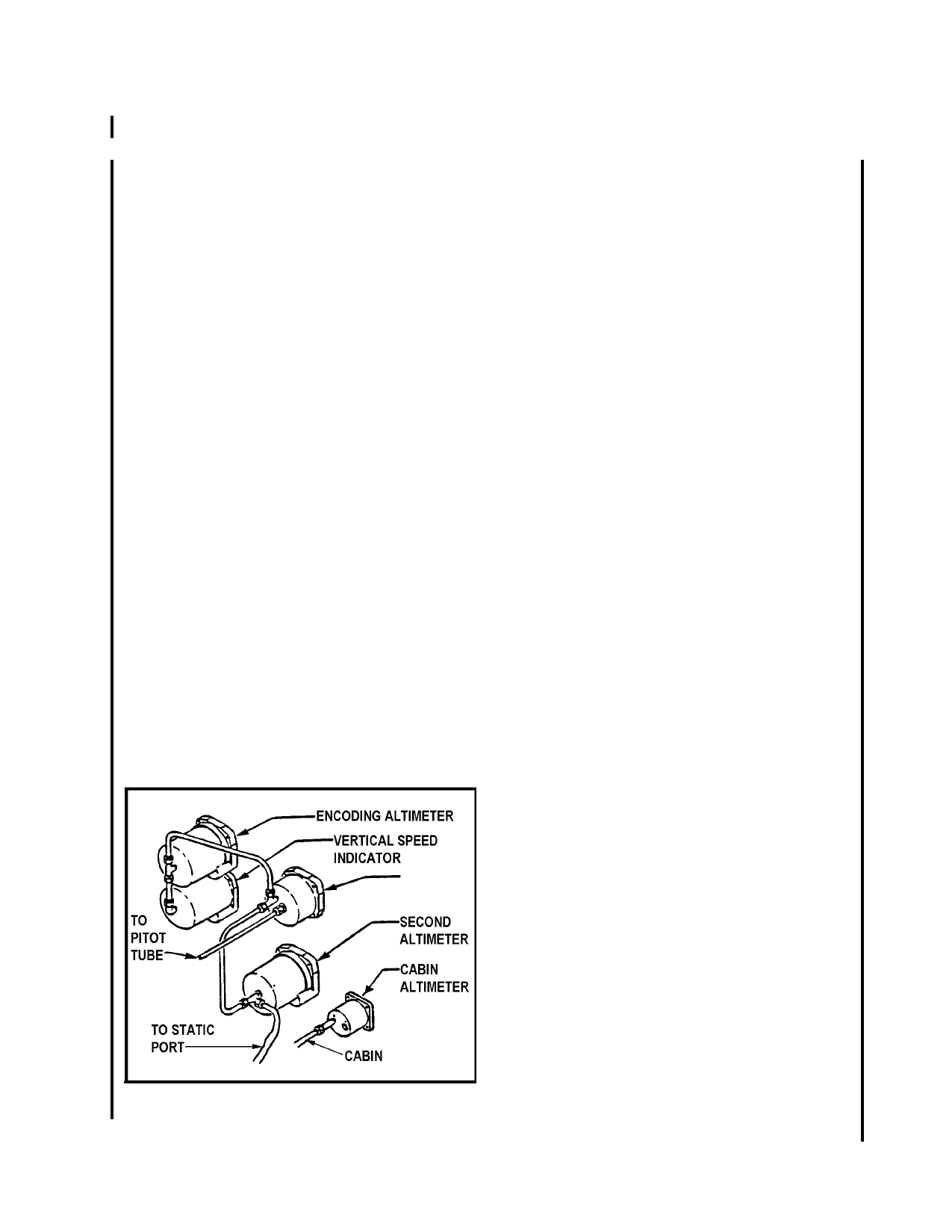
12-52. SYSTEM COMPONENTS. The
conventional design of the pitot system con
sists of pitot-static tubes or pitot tubes with
static pressure parts and vents, lines, tubing,
water drains and traps, selector valves, and
various pressure-actuated indicators or control
units such as the altimeter, airspeed and rate
of-climb indicators, and the encoding altimeter
connected to the system. (See figure 12-5.)
Inspect for elevation or depression of the port
or vent fitting. Such elevation or depression
may cause airflow disturbances at high speeds
and result in erroneous airspeed and altitude
indications.
12-55. HEATER ELEMENTS. A heating
element is located within the tube head to pre
vent the unit from becoming clogged during
icing conditions experienced during flight. A
switch in the cockpit controls the heater.
Some pitot-static tubes have replaceable heater
elements while others do not. Check the
heater element or the entire tube for proper op
eration by noting either ammeter current or
that the tube or port is hot to the touch. (See
figure 12-6.)
12-56. SYSTEM INSPECTION.
Figure 12-5. Pitot/static system for a small aircraft.
a. Inspect air passages in the systems for
water, paint, dirt or other foreign matter. If
water or obstructive material has entered the
system, all drains should be cleaned. Probe
the drains in the pitot tube with a fine wire to
remove dirt or other obstructions. The bottom
static openings act as drains for the head’s
static chamber. Check these holes at regular
intervals to preclude system malfunctioning.
Par 12-51
Page 12-19