FAA Advisory Circular 43.13-1B
Acceptable Methods, Techniques, and Practices
Aircraft Inspection and Repair
AC 43.13-1B | 12. Aircraft Avionics Systems | 3. Ground Operational Checks for Avionics Equipment (Non-Electrical) | 12-38. Pneumatic Gyros
9/27/01
AC 43.13-1B CHG 1
12-38. PNEUMATIC GYROS.
a. Venturi Systems. The early gyro in
struments were all operated by air flowing out
of a jet over buckets cut into the periphery of
the gyro rotor. A venturi was mounted on the
outside of the aircraft to produce a low pres
sure, or vacuum, which evacuated the instru
ment case, and air flowed into the instrument
through a paper filter and then through a noz
zle onto the rotor.
(1) Venturi systems have the advantage
of being extremely simple and requiring no
power from the engine, nor from any of the
other aircraft systems; but they do have the
disadvantage of being susceptible to ice, and
when they are most needed, they may become
unusable.
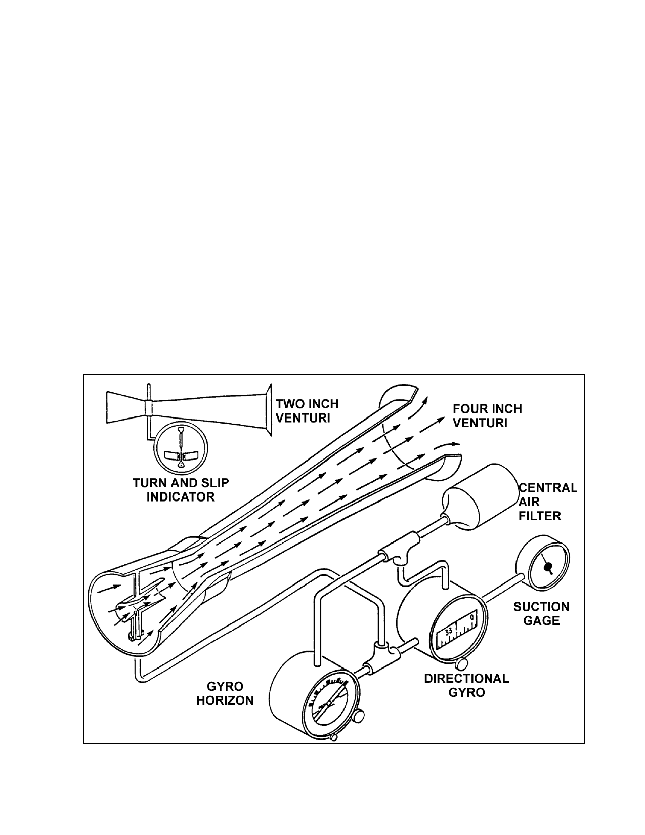
(2) There are two sizes of venturi tubes:
those which produce four inches of suction are
used to drive the attitude gyros, and smaller
tubes, which produce two inches of suction,
are used for the turn and slip indicator. Some
installations use two of the larger venturi tubes
connected in parallel to the two attitude gyros,
and the turn and slip indicator is connected to
one of these instruments with a needle valve
between them. A suction gage is temporarily
connected to the turn and slip indicator, and
the aircraft is flown so the needle valve can be
adjusted to the required suction at the instru
ment when the aircraft is operated at its cruise
speed. (See figure 12-1.)
FIGURE 12-1. Venturi system for providing airflow through gyro instruments.
Par 12-38
Page 12-15