FAA Advisory Circular 43.13-1B
Acceptable Methods, Techniques, and Practices
Aircraft Inspection and Repair
AC 43.13-1B | 11. Aircraft Electrical Systems | 17. Connectors | 11-237. Special Purpose Connector
AC 43.13-1B
9/8/98
moisture in the connectors. A secondary bene-
fit of potting is the reduced possibility of
breakage between the contact and wire due to
vibration.
a. Connectors specifically designed for
potting compounds should be potted to pro-
vide environment resistance. An o-ring or
sealed gasket should be included to seal the
interface area of the mated connector. A plas-
tic potting mold, that remains on the connector
after the potting compounds have cured,
should also be considered. To facilitate circuit
changes, spare wires may be installed to all
unused contacts prior to filling the connector
with potting compound.
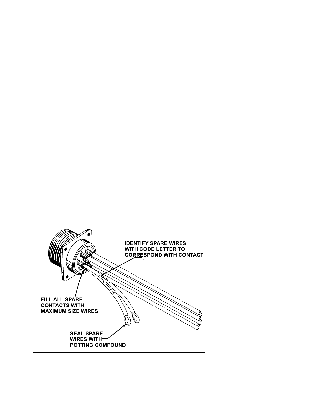
b. Connect wires to all contacts of the
connector prior to the application of the pot-
ting compound. Wires that are not to be used
should be long enough to permit splicing at a
later date. Unused wires should be as shown
in figure 11-38 and the cut ends capped with
heat-shrinkable caps or crimped insulated end
caps such as the MS 25274 prior to securing to
the wire bundle. Clean the areas to be potted
with dry solvent and complete the potting op-
eration within 2 hours after this cleaning. Al-
low the potting compound to cure for 24 hours
at a room temperature of 70 °F to 75 °F or
carefully placed in a drying oven at 100 °F for
3 to 4 hours. In all cases follow manufac-
turer’s instructions.
11-240. THROUGH BOLTS. Through
bolts are sometimes used to make feeder con-
nections through bulkheads, fuselage skin, or
firewalls. Mounting plates for through bolts
must be a material that provides the necessary
fire barrier, insulation, and thermal properties
for the application. Sufficient cross section
should be provided to ensure adequate con-
ductivity against overheating. Secure through
bolts mechanically and independently of the
terminal mounting nuts, taking particular care
to avoid dissimilar metals among the terminal
hardware. During inspection, pay particular
attention to the condition of the insulator plate
or spacer and the insulating boot that covers
the completed terminal assembly.
FIGURE 11-38. Spare wires for potting connector.
11-241.11-247. [RESERVED.]
Page 11-98
Par 11-235