FAA Advisory Circular 43.13-1B
Acceptable Methods, Techniques, and Practices
Aircraft Inspection and Repair
AC 43.13-1B | 11. Aircraft Electrical Systems | 16. Wire Marking | 11-217. Installation of Printed Sleeves
AC 43.13-1B CHG 1
9/27/01
specify which color is associated with each
wire identification code. Identification sleeves
are normally used for identifying the following
types of wire or cable:
11-216. OPERATING CONDITIONS. For
sleeving exposed to high temperatures (over
400 °F), materials such as silicone fiberglass
should be used.
a. Unjacketed shielded wire.
b. Thermocouple wire identification is
normally accomplished by means of identifi
cation sleeves. As the thermocouple wire is
usually of the duplex type (two insulated wires
within the same casing), each wire at the ter
mination point bears the full name of the con
ductor. Thermocouple conductors are alumel,
chromel, iron, constantan, and copper
constantan.
c. Coaxial cable should not be hot
stamped directly. When marking coaxial ca
ble, care should be taken not to deform the ca
ble as this may change the electrical charac
teristics of the cable. When cables cannot be
printed directly, they should be identified by
printing the identification code (and individual
wire color, where applicable) on a nonmetallic
material placed externally to the outer covering
at the terminating end and at each junction or
pressure bulkhead. Cables not enclosed in
conduit or a common jacket should be identi
fied with printed sleeves at each end and at
intervals not longer than 3 feet. Individual
wires within a cable should be identified
within 3 inches from their termination.
d. Multiconductor cable normally use
identification sleeves for identifying un
shielded, unjacketed cable.
e. High-temperature wire with insulation
is difficult to mark (such as Teflon and fiber
glass).
11-217. INSTALLATION OF PRINTED
SLEEVES. Polyolefin sleeving should be
used in areas where resistance to solvent and
synthetic hydraulic fluids is necessary. Sleeves
may be secured in place with cable ties or by
heat shrinking. The identification sleeving for
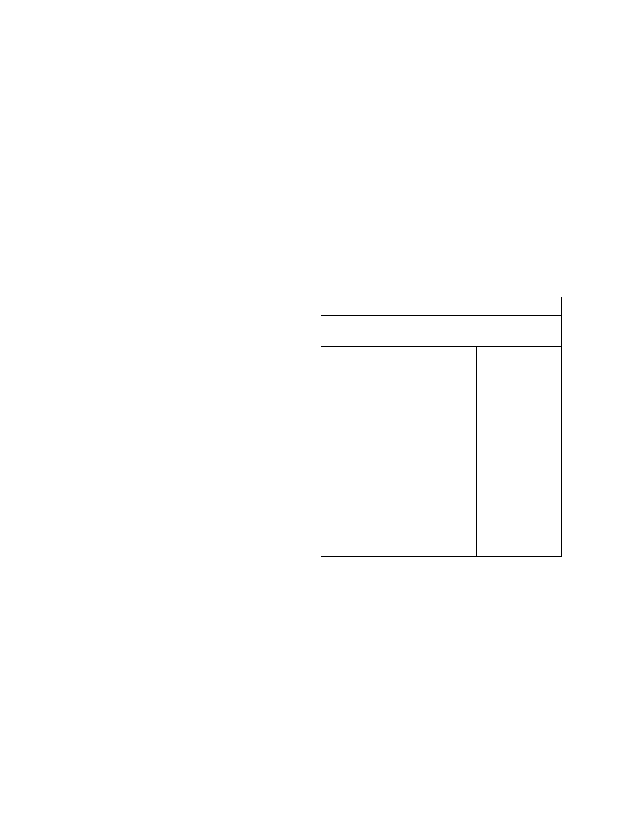
various sizes of wire is shown in table 11-17.
Table 11-17. Recommended size of identification
sleeving.
Wire Size
Sleeving Size
AN
AL
No.
Nominal ID
(inches)
#24
12
.085
#22
11
.095
#20
10
.106
#18
9
.118
#16
8
.113
#14
7
.148
#12
6
.166
#10
4
.208
#8
#8
2
.263
#6
#6
0
.330
#4
#4
3/8 inch
.375
#2
#2
1/2 inch
.500
#1
#1
1/2 inch
.500
#0
#0
5/8 inch
.625
#00
#00 5/8 inch
.625
#000
#000 3/4 inch
.750
#0000
#0000 3/4 inch
.750
11-218. IDENTIFICATION OF WIRE
BUNDLES AND HARNESSES. The identi
fication of wire bundles and harnesses is be
coming a common practice and may be ac
complished by the use of a marked sleeve tied
in place or by the use of pressure-sensitive tape
as indicated in figure 11-25.
11-215. IDENTIFICATION TAPE. Identi
fication tape can be used in place of sleeving,
in most cases (i.e. polyvinylfluoride).
Page 11-86
Par 11-220