FAA Advisory Circular 43.13-1B
Acceptable Methods, Techniques, and Practices
Aircraft Inspection and Repair
AC 43.13-1B | 11. Aircraft Electrical Systems | 13. Splicing | 11-167. General
9/8/98
SECTION 13. SPLICING.
AC 43.13-1B
11-167. GENERAL. Splicing is permitted
on wiring as long as it does not affect the reli-
ability and the electromechanical characteris-
tics of the wiring. Splicing of power wires,
coaxial cables, multiplex bus, and large gauge
wire must have approved data.
a. Splicing of electrical wire should be
kept to a minimum and avoided entirely in
locations subject to extreme vibrations.
Splicing of individual wires in a group or bun-
dle should have engineering approval and the
splice(s) should be located to allow periodic
inspection.
b. Many types of aircraft splice connec-
tors are available for use when splicing indi-
vidual wires. Use of a self-insulated splice
connector is preferred; however, a noninsu-
lated splice connector may be used provided
the splice is covered with plastic sleeving that
is secured at both ends. Environmentally
sealed splices, that conform to MIL-T-7928,
provide a reliable means of splicing in
SWAMP areas. However, a noninsulated
splice connector may be used, provided the
splice is covered with dual wall shrink
sleeving of a suitable material.
c. There should not be more than one
splice in any one wire segment between any
two connectors or other disconnect points, ex-
cept; when attaching to the spare pigtail lead of
a potted connector, to splice multiple wires to
a single wire, to adjust wire size to fit connec-
tor contact crimp barrel size, and to make an
approved repair. (Reference MIL-W-5088,
now AS50881A, and NAVAIR 01-1A-505.)
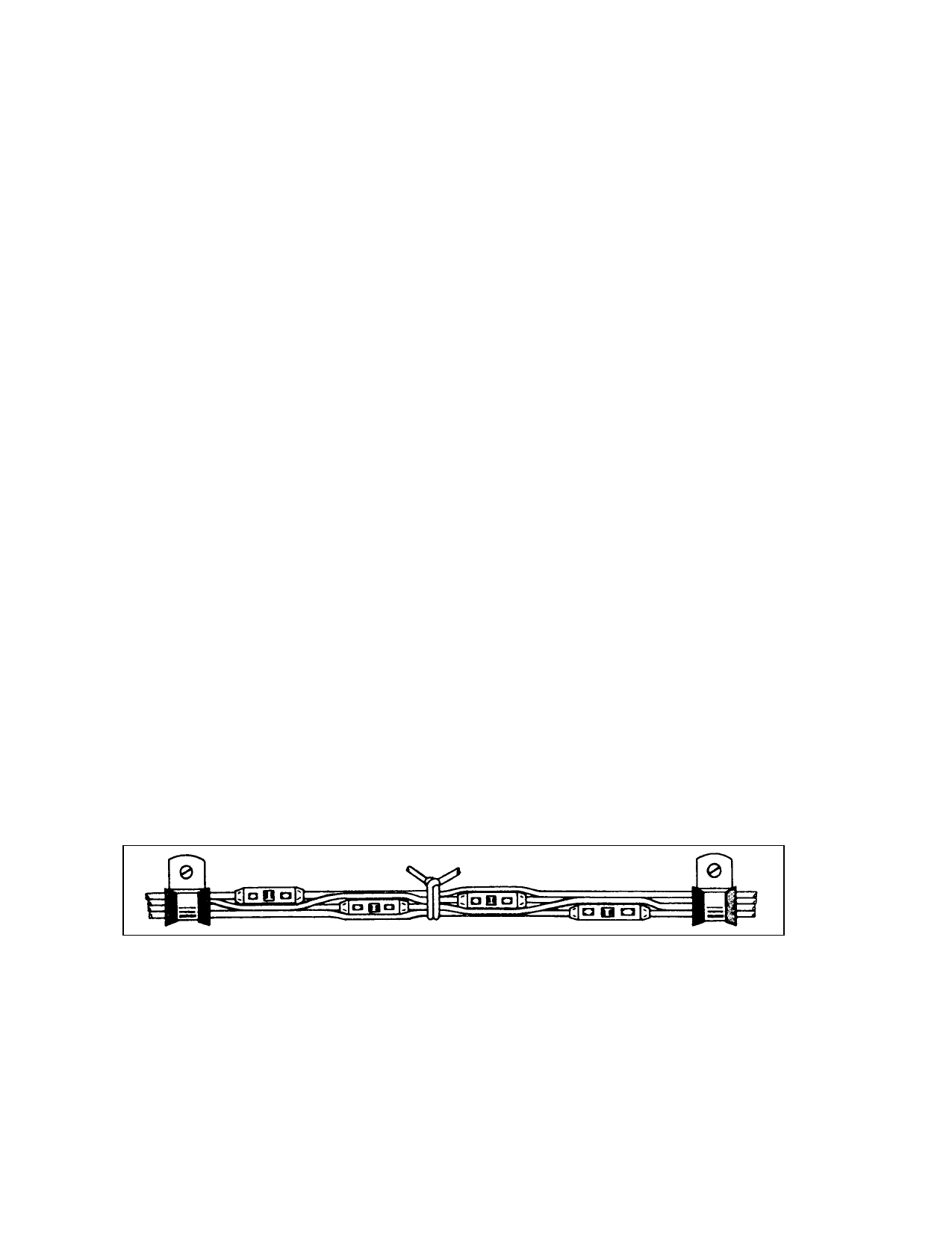
d. Splices in bundles must be staggered
so as to minimize any increase in the size of
the bundle, preventing the bundle from fitting
into its designated space, or cause congestion
that will adversely affect maintenance. (See
figure 11-18.)
e. Splices should not be used within
12 inches of a termination device, except for
paragraph f below.
f. Splices may be used within 12 inches
of a termination device when attaching to the
pigtail spare lead of a potted termination de-
vice, or to splice multiple wires to a single
wire, or to adjust the wire sizes so that they are
compatible with the contact crimp barrel sizes.
g. Selection of proper crimping tool, re-
fer to paragraph 11-178.
FIGURE 11-18. Staggered splices in wire bundle.
11-168.11-173. [RESERVED.]
Par 11-167
Page 11-65 (and 11-66)